As of August 07, 2025, the global telecommunications industry is witnessing unprecedented growth, with fiber optic cables underpinning 5G networks, smart cities, and high-speed internet. Among these, armored and unarmored fiber optic cables offer distinct solutions based on their protective design. This guide compares armored and unarmored cables, exploring their construction, performance metrics, applications, and deployment challenges. Tailored for professionals sourcing from CommMesh, it provides insights to optimize network resilience in today’s demanding environment.
Introduction to Armored and Unarmored Fiber Optic Cables
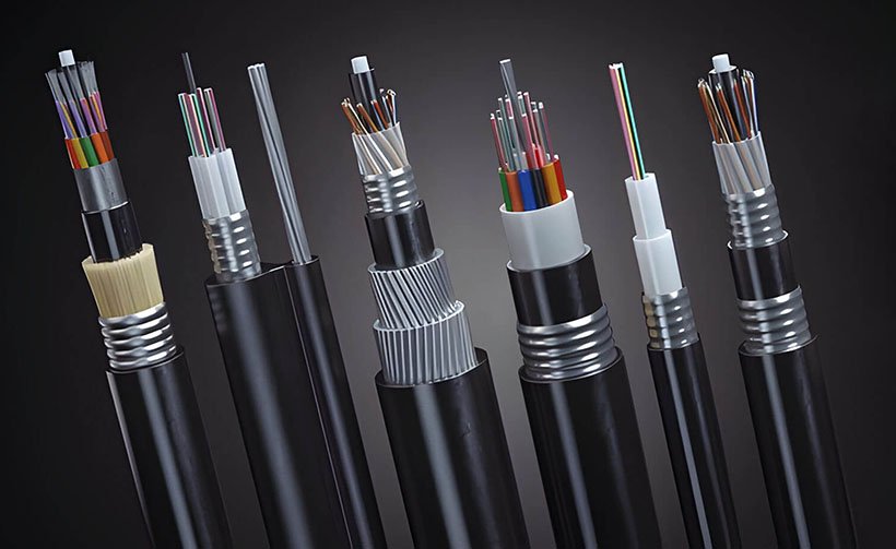
Fiber optic cables transmit data as light pulses through a core, offering bandwidths up to 400 Gbps per fiber via wavelength-division multiplexing (WDM). The key difference between armored and unarmored cables lies in their protective layers: armored cables feature additional metal shielding (e.g., steel tape or corrugated steel), while unarmored cables rely on polymer jackets. This distinction impacts their durability, cost, and suitability for various environments. As of August 2025, with over 1.7 million km of fiber deployed globally (per TeleGeography), choosing the right cable type is critical for long-term network performance.
Construction Comparison
The construction of armored and unarmored cables reflects their intended resilience:
- Optical Fiber (Core and Cladding)
- Both types use a core (8–62.5 μm) and cladding (125 μm), made of silica with a refractive index of 1.46 (core) and 1.44 (cladding) for total internal reflection.
- Armored: Typically single-mode (8–10 μm) for long-haul (0.2 dB/km loss).
- Unarmored: Often multimode (50–62.5 μm) for short runs (1–3 dB/km loss).
- Technical Note: Core purity (99.9999% silica) ensures minimal scattering in both.
- Buffer Coating
- Armored: A 250–900 μm acrylate buffer provides 600–1000 N tensile strength, resisting -40°C to 70°C and moisture.
- Unarmored: A 250–500 μm buffer offers 500–800 N strength, optimized for controlled indoor conditions (0°C to 60°C).
- Difference: Armored buffers are thicker to handle external stress.
- Strength Members
- Armored: Aramid yarn or fiberglass rods (1000–3000 N) support heavy loads during burial or aerial use (e.g., 50 kN/m² soil pressure).
- Unarmored: Lighter aramid yarn (500–1000 N) suits indoor pulls or light outdoor use.
- Difference: Armored members enhance durability for rugged terrains.
- Jacket
- Armored: Polyethylene with steel tape or corrugated steel (5–10 mm thick) provides UV resistance, IP68 water protection (0.1 MPa), and 1000 N extra strength.
- Unarmored: PVC or LSZH jackets (2–5 mm) focus on flexibility, with 500 N strength and 0.05 MPa water resistance.
- Difference: Armored jackets add 20–30% weight for protection.
- Armor Layer
- Armored: A steel tape or corrugated steel layer (0.2–0.5 mm thick) adds 1000–2000 N crush resistance and rodent protection.
- Unarmored: No armor, relying on the jacket for protection.
- Difference: Armor increases durability but raises cost by 30–50%.
| Component | Armored | Unarmored | Key Difference |
|---|---|---|---|
| Core Type | Single-Mode (8–10 μm) | Multimode (50–62.5 μm) | Distance vs. cost |
| Buffer Thickness | 250–900 μm | 250–500 μm | Durability vs. flexibility |
| Strength Members | 1000–3000 N | 500–1000 N | Load capacity |
| Jacket Material | PE, Steel Tape | PVC, LSZH | Protection vs. safety |
| Armor Layer | Steel Tape/Corrugated | None | Crush resistance |

Performance Comparison
Performance metrics underscore their design goals:
- Attenuation and Distance
- Armored: 0.2–0.4 dB/km for single-mode, supporting 100 km without repeaters, ideal for backbone networks.
- Unarmored: 1–3 dB/km for multimode, limited to 2 km, suited for LANs.
- Difference: Armored cables prioritize long-haul efficiency.
- Bandwidth
- Armored: Up to 400 Gbps per fiber with WDM, supporting 128 channels at 1310/1550 nm.
- Unarmored: 10–100 Gbps, sufficient for 100-meter indoor links.
- Difference: Armored bandwidth scales for high-capacity routes.
- Environmental Tolerance
- Armored: -40°C to 70°C, 1000–2000 N/cm crush resistance, and 0.1 MPa water pressure tolerance.
- Unarmored: 0°C to 60°C, 500 N/cm crush resistance, and minimal water exposure.
- Difference: Armored cables endure extreme conditions.
- Durability
- Armored: 20–30 year lifespan, resisting 50 kN/m² soil pressure and rodent damage.
- Unarmored: 10–20 years in controlled settings, vulnerable to 10 N/cm pressure.
- Difference: Armored longevity suits infrastructure needs.

Applications Comparison
The applications of armored and unarmored fiber optic cables reflect their protective designs:
- Armored Fiber Optic Cables
- Long-Haul and Backbone Networks: Single-mode armored cables support 100 km runs with 0.2 dB/km loss, ideal for transcontinental links. Example: A 2025 China Telecom project deployed 6000 km of armored loose-tube cables for 5G backbone.
- Harsh Outdoor Environments: Steel-tape armored cables resist 1000–2000 N/cm crush loads, used in buried (1.0–1.5 m) or aerial installations near power lines.
- Industrial Settings: Rodent-proof designs protect against 10 N chewing force, supporting 30% of industrial fiber growth (per CRU Group 2025).
- Technical Note: Tensile strength of 3000 N handles 200 m aerial spans.
- Unarmored Fiber Optic Cables
- Data Centers: Multimode unarmored cables (50 μm) deliver 100 Gbps over 100 meters, with 144-core ribbon designs saving 40% duct space. Microsoft’s 2025 data center in Virginia uses 96-core unarmored cables.
- Indoor Building Backbones: Tight-buffered cables connect floors, supporting 10 Gbps LANs with 0.3 m conduit runs.
- FTTH Drops: Flexible unarmored designs simplify home installations, reducing labor by 50% (per FTTH Council 2025).
- Technical Note: 500 N strength suits 10 mm bend radii.
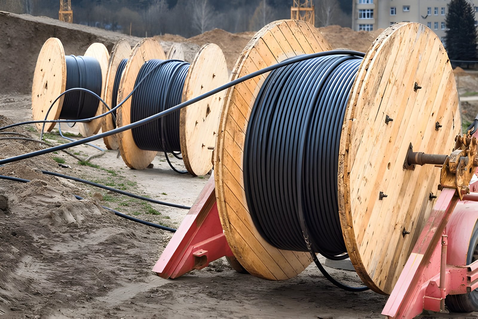
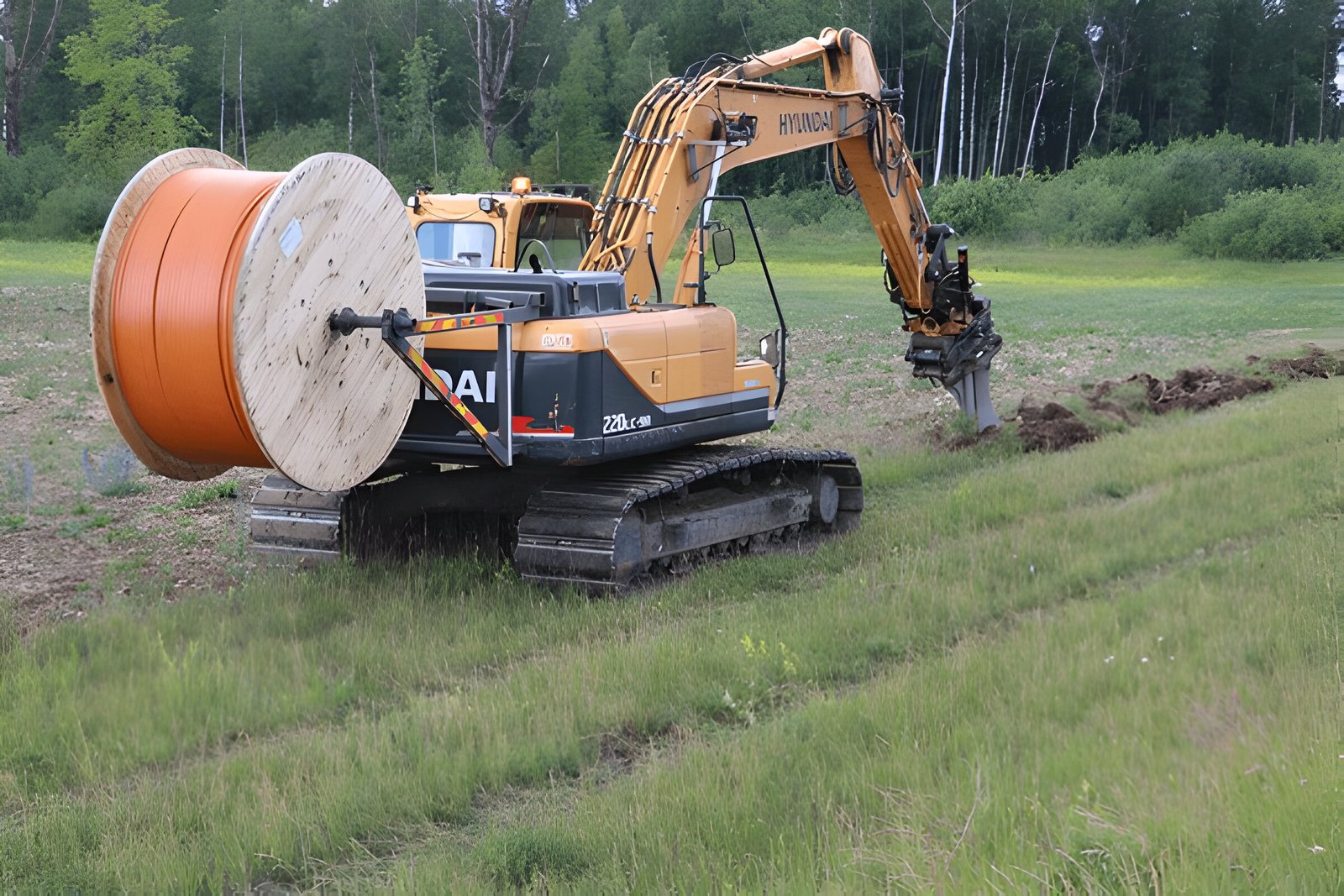
Installation Considerations Comparison
Installation practices vary with cable type:
- Armored Fiber Optic Cables
- Burial Depth: 0.9–1.5 meters, below frost lines (e.g., 1.2 m in Canada), resisting 50 kN/m² soil pressure.
- Trenching and Splicing: Requires heavy machinery and fusion splicing (0.01–0.05 dB loss), taking 10–15 minutes per joint with a fiber optic splicer machine.
- Environmental Prep: Steel armor and water-blocking gel protect against -40°C to 70°C and 0.1 MPa water pressure.
- Technical Note: OTDR testing at 1310/1550 nm ensures <0.2 dB/km loss, with 1000 N/cm crush tests post-installation.
- Unarmored Fiber Optic Cables
- Conduit Runs: 0.1–0.3 meters in walls or ceilings, with 10–20 mm bend radii to avoid 0.01% loss.
- Termination: Plug-and-play or mechanical splicing (0.1–0.3 dB loss) takes 5–7 minutes, using LC/SC connectors.
- Environmental Prep: LSZH jackets reduce smoke by 90% in fire scenarios; no gel needed indoors.
- Technical Note: Power meters verify <1 dB/km loss, with 500 N/cm crush tests.
Cost Analysis Comparison
Cost differences influence deployment decisions:
- Armored Fiber Optic Cables
- Material Cost: $0.80–$3.00/meter, with steel tape adding $0.50–$1.00/meter.
- Installation Cost: $600–$1200/km, including trenching and splicing labor.
- Lifespan Cost: 20–30 years, with 10% maintenance (e.g., $60/km/year) for repairs.
- Example: A 2025 rural project in Australia spent $3 million for 2500 km.
- Unarmored Fiber Optic Cables
- Material Cost: $0.30–$1.00/meter, as LSZH and tight buffering are cheaper.
- Installation Cost: $200–$500/km, with simpler conduit runs and terminations.
- Lifespan Cost: 10–20 years, with 5% maintenance (e.g., $20/km/year).
- Example: A 2025 office build in Singapore cost $150,000 for 300 km.
| Aspect | Armored | Unarmored | Difference |
|---|---|---|---|
| Material Cost | $0.80–$3.00/meter | $0.30–$1.00/meter | 166–300% higher armored |
| Installation Cost | $600–$1200/km | $200–$500/km | 200–240% higher armored |
| Lifespan Cost | 20–30 years, 10% maint. | 10–20 years, 5% maint. | Longer armored durability |
Challenges Comparison
Each type faces unique obstacles:
- Armored Fiber Optic Cables
- Weight and Flexibility: 20–30% heavier (e.g., 150 kg/km vs. 100 kg/km), limiting bend radius to 30 mm. Solution: Use flexible steel tape designs.
- Installation Complexity: Trenching at 1.5 m depth increases labor by 30%. Solution: Micro-trenching reduces costs by 20%.
- Cost: Higher upfront investment ($3 million/2500 km). Solution: Bulk orders save 15%.
- Unarmored Fiber Optic Cables
- Environmental Vulnerability: Susceptible to 10 N/cm rodent damage and 0.05 MPa water pressure. Solution: Conduit protection or hybrid designs.
- Fire Risk: PVC jackets emit toxic smoke. Solution: LSZH reduces toxicity by 90%.
- Durability: 10–20 year lifespan limits long-term use. Solution: Scheduled upgrades every 10 years.
Future Trends Comparison
Innovations as of August 2025 shape both types:
- Armored Fiber Optic Cables
- Higher Core Counts: 288-core armored cables with 115 Tbps capacity are in testing, targeting 2026 rural deployments.
- Lightweight Armor: Aluminum-based armor reduces weight by 15%, enhancing aerial use.
- Automation: Robotic trenching systems aim for 50 m/hour, cutting labor by 30%.
- Unarmored Fiber Optic Cables
- Smart Fibers: IoT sensors monitor 0.01 dB loss in real-time, boosting data center efficiency by 15%.
- Miniaturization: 1 mm diameter cables for 5G in-building use are in development, saving 50% space.
- Fire Safety: Halogen-free materials reduce smoke by 95%, per 2025 safety codes.
Conclusion
Armored and unarmored fiber optic cables cater to distinct needs in August 2025’s network landscape. Armored cables, with steel tape and robust construction, excel in outdoor long-haul and harsh environments, offering 100 km runs with 0.2 dB/km loss and 20–30 year durability. Unarmored cables, with flexible LSZH jackets, optimize indoor short-range applications like data centers and FTTH, with 10–20 year lifespans. Their cost, installation, and performance differences guide deployment choices, while future trends like higher core counts and smart sensors promise enhanced capacity and efficiency. For tailored solutions, explore CommMesh.
