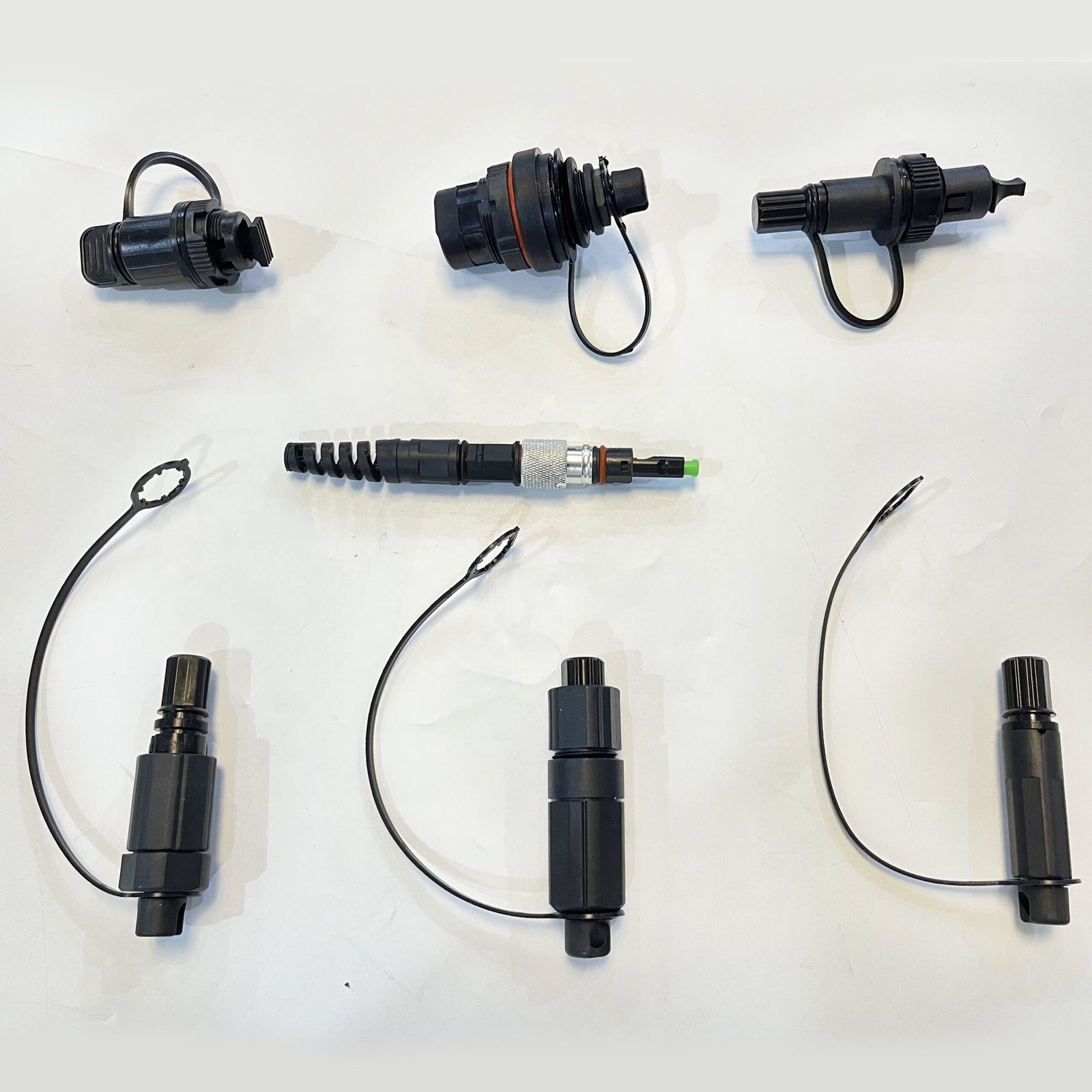
Key benefits of OptiTap-style connectors include:
- Rapid Deployment: Plug-and-play reduces installation time by up to 80% compared to traditional splicing.
- High Performance: Typical insertion loss <0.3 dB, return loss >60 dB on SM G.657A2 fiber.
- Kesesuaian: Direct mating with Corning MST terminals and hybrids for Huawei Mini-SC, Furukawa, and standard SC/APC.
- Daya tahan: 500+ mating cycles, -40°C to +85°C operation, waterproof gel or mechanical seals.
China dominates global production of OptiTap-compatible connectors and pre-terminated assemblies. Chinese manufacturers combine advanced automation, vertical integration of ferrules, cables, and housings, and massive scale to offer cost savings of 30-60% versus Western OEMs while meeting or exceeding IEC, Telcordia, GR-326, and RoHS standards. Many factories export to Southeast Asia, Africa, Europe, and Latin America, supporting major telecom operators worldwide.
This in-depth guide ranks the leading China OptiTap connector manufacturers in 2026. Rankings consider production capacity, innovation (especially universal/3-in-1 designs), quality certifications, customization, export volume, R&D investment, and real-world customer feedback.
Whether you need bulk OEM supply, custom pre-connectorized cables, or universal solutions for multi-vendor networks, this article provides the details to make informed sourcing decisions.
Why Source OptiTap Connectors from China?
- Efisiensi Biaya: High-volume production lowers per-unit costs without sacrificing quality.
- Skalabilitas: Facilities producing millions of units annually with short lead times (7-21 days for customs).
- Innovation in Universality: 3-in-1 and multi-compatible housings reduce inventory SKUs.
- Full Supply Chain: From raw fiber and ceramic ferrules to finished assemblies and enclosures.
- Compliance & Testing: ISO 9001/14001, full environmental and optical testing labs.
- Kustomisasi: Cable types (flat drop, round, toneable, armored), lengths, colors, pulling grips.
Now, the ranked list of top China OptiTap connector manufacturers.
1. GL Technology Co., Ltd. (Hunan GL)
GL Technology, headquartered in Changsha, Hunan Province, stands as one of China’s most experienced and largest-scale OptiTap fiber connector manufacturers. With over 16 years in the fiber optic industry, GL operates modern facilities focused on end-to-end production of cables and connectors. They specialize in OptiTap-compatible solutions for global FTTH projects.
Company Background and Scale: Founded in the early 2000s, GL has grown into a vertically integrated powerhouse with multiple production lines for fiber cables, connectors, and assemblies. Their workforce exceeds 1,000 employees, including a dedicated R&D team of optical engineers. Annual capacity for hardened connectors and pre-terminated drops reaches several million units, supported by automated polishing, assembly, and testing equipment in Class 1000 cleanrooms.
Key Products and Technical Excellence:
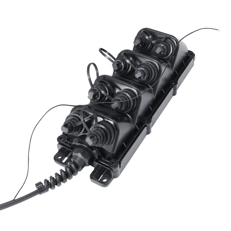
- OptiTap-compatible hardened connectors with precise twist-lock mechanisms for seamless Corning MST integration.
- Pre-terminated FTTH drop cables on G.657A2 bend-insensitive fiber, available in flat or round profiles, toneable versions, and various lengths (50m to 500m+).
- Hybrid assemblies: OptiTap to SC/APC pigtails or multi-port configurations.
- Field-installable options with factory-polished ferrules for on-site flexibility.
- IP68-rated performance with superior sealing against water ingress and dust.
GL’s products achieve industry-leading optical specs: average insertion loss of 0.2 dB or better and high return loss. They undergo rigorous testing including thermal cycling, vibration, salt spray, and long-term aging to ensure reliability in tropical, desert, or coastal deployments.
Manufacturing and Quality Assurance: GL employs AI-powered inspection systems for 99.9% yield rates. Full traceability from ceramic ferrule production to final packaging. Certifications include ISO 9001, ISO 14001, and compliance with international telecom standards. Their R&D focuses on improving mating durability and reducing attenuation in high-density setups.
Market Position and Customer Success: GL supplies major domestic carriers and international projects across Asia, Africa, and the Middle East. Clients praise their consistent quality, competitive pricing, and responsive technical support. One notable deployment involved hundreds of thousands of units for a national broadband initiative, achieving near-zero failure rates during installation.
Why #1: Unmatched scale, proven track record, and strong emphasis on core OptiTap compatibility make GL the preferred volume supplier for large operators and distributors. Their vertical integration ensures supply chain stability even during global shortages.
2. DEKAM FIBER
Dekam Fiber, a leading specialist in hardened connectivity solutions, excels in IP68 waterproof connectors and pre-connectorized systems. Based in a high-tech hub, they have built a strong reputation for innovation in multi-compatible designs and harsh-environment performance.
Detailed Profile: With years of focused R&D in FTTA and FTTH accessories, Dekam operates advanced extrusion and connector assembly lines. They emphasize compatibility across ecosystems, serving both OEM and custom B2B clients globally.
Signature Offerings:
- 3-in-1 hardened connectors compatible with Corning OptiTap, Huawei Mini-SC, and standard interfaces.
- Pre-terminated drop cables with pulling grips, armored options, and LSZH jackets.
- Full range of accessories: adapters, closures, MST boxes, and tools.
- Field-assembly connectors for flexible deployments.
Kekuatan:
- Proven long-term performance in South America and other challenging climates.
- Emphasis on mechanical robustness and optical stability.
- Fast customization turnaround and excellent customer collaboration.
3. Hengtong Optic-Electric Co., Ltd. (Part of Hengtong Group)
Hengtong Optic-Electric, a giant in the global fiber optic sector, brings massive resources and technological depth to OptiTap-compatible manufacturing. As a key player in China’s optical communication ecosystem, they integrate connector production with their world-class fiber and cable capabilities.
Overview and Capabilities: Part of a larger group with extensive R&D centers, Hengtong produces high-volume hardened connectors alongside comprehensive ODN solutions. Their scale supports mega-projects for operators worldwide.
Product Highlights:
- High-precision OptiTap clones and hybrids.
- Integrated pre-connectorized systems for rapid rollout.
- Advanced materials for extended lifespan and lower total cost of ownership.
Keuntungan: Global brand recognition, stringent quality controls, and ability to bundle with fibers, cables, and enclosures. Strong in Asia-Pacific and emerging markets.
4. CommMesh – Innovative Universal OptiTap Solutions Leader
KomunikasiMesh earns its position as a top-tier China OptiTap connector manufacturer through specialization in flexible, universal designs that address real-world multi-vendor challenges in modern FTTH deployments. Operating from Guangzhou with a modern facility and over 200 employees, CommMesh focuses on high-customization and interoperability, making it a preferred partner for ISPs and integrators seeking agility.
Company Background: CommMesh has rapidly established itself by prioritizing customer pain points like inventory complexity and vendor lock-in. Their state-of-the-art lines support hundreds of thousands of assemblies per month, backed by significant R&D investment.
Flagship Products and Innovations:
- 3-in-1 Universal OptiTap Compatible Connector: The standout feature—an interchangeable housing that mates seamlessly with Corning OptiTap MST ports, Huawei Mini-SC, and standard SC/APC terminals. This single solution reduces SKU variety and inventory costs by up to 40%, ideal for brownfield upgrades and mixed networks.
- Pre-terminated FTTH drop cables: Flat-drop, toneable, armored variants on G.657A2 fiber, with options for custom lengths, colors, and pulling grips.
- IP68-rated, UV-stabilized assemblies designed for aerial, duct, or buried use.
- Hybrid patch cords and field-installable variants for maximum flexibility.
Manufacturing Excellence: Automated processes ensure high throughput and 99.8%+ yield. Emphasis on precision ferrules and robust sealing delivers <0.3 dB insertion loss and excellent return loss. Full compliance with international standards, plus in-house labs for environmental, mechanical, and optical validation.
What Distinguishes CommMesh:
- Customization Prowess: Rapid prototyping (as fast as 2 weeks) for tailored solutions matching specific fiber types (e.g., SMF-28 equivalents) or project requirements.
- Deployment Efficiency: Plug-and-play designs dramatically cut installation time and labor, with proven reliability in diverse climates.
- Global Orientation: Exports supporting projects in 100+ countries, with strong technical support and logistics.
- Value Proposition: Competitive pricing combined with premium features positions CommMesh as the smart choice for forward-thinking buyers avoiding rigid single-brand systems.
Real-World Applications and Testimonials: In Southeast Asian deployments, CommMesh’s universal connectors enabled seamless integration across legacy and new infrastructure, saving operators significant time and money. Clients highlight ease of use, durability, and responsive service as key advantages.
For buyers on commmesh.com seeking innovative China OptiTap solutions, CommMesh delivers exceptional adaptability without compromising performance or compliance. Their focus on universality makes them particularly valuable in today’s heterogeneous network environments.
5. Optico Communication Co., Ltd. (Shenzhen Optico)
Optico Communication, based in Shenzhen, Guangdong Province, is a precision-focused China OptiTap connector manufacturer known for high-quality fiber optic components and assemblies. Established in the early 2000s, Optico has built a strong reputation among international buyers for reliable hardened connectors and customization capabilities. Their modern facilities emphasize cleanroom production and rigorous testing, supporting both standard and bespoke OptiTap-compatible solutions for FTTH and FTTA projects.
Company Strengths and Scale: With hundreds of employees and dedicated optical engineering teams, Optico maintains full production lines for connectors, patch cords, and pre-terminated cables. While not the largest in raw volume, their focus on precision engineering yields consistently low-defect products suitable for high-end deployments.
Key Products:
- OptiTap-compatible hardened connectors with excellent mating compatibility to Corning MST ports.
- 3-in-1 hybrid designs for multi-vendor flexibility.
- Pre-terminated drop cables in various configurations (flat drop, round, armored).
- Field-installable and fusion splice-on variants.
- Full accessory ecosystem including adapters, closures, and tools.
Technical and Quality Edge: Optico uses premium ceramic ferrules and advanced polymer housings to achieve superior optical performance (<0.25 dB typical insertion loss) and mechanical durability. Products undergo extensive environmental testing (IP68 waterproofing, thermal shock, UV aging) in in-house labs. Certifications cover ISO 9001 and compliance with GR-326, IEC standards.
Market Reach and Advantages: Optico excels in rapid prototyping and small-to-medium batch customization, making them ideal for specialized projects or distributors needing unique specs (e.g., specific cable jackets or color coding). Clients appreciate their responsive support and consistent quality, which reduces field failures and long-term maintenance costs. Their location in Shenzhen facilitates efficient global shipping and supply chain integration.
This positions Optico as a strong mid-tier choice for buyers balancing quality, flexibility, and competitive pricing in the China OptiTap market.
6. Yingfeng Optical Communication (Yingfeng)
Yingfeng is a specialized passive optical component manufacturer with significant capabilities in hardened connectors. They focus on high-volume production of SC/APC-based and OptiTap-compatible solutions, serving both domestic Chinese operators and export markets. Their vertical integration from ferrules to finished assemblies ensures tight quality control and cost efficiency.
Profile Highlights:
- Strong emphasis on FTTH accessories and pre-connectorized solutions.
- Capacity for large-scale orders with reliable lead times.
- Innovations in sealing technology and ease-of-install features.
- Proven track record in bundled ODN (Optical Distribution Network) solutions.
7. T&S Communication Co., Ltd.
T&S Communication stands out for advanced fiber optic components and high-density solutions. With a history of innovation, they bring expertise in VSFF (Very Small Form Factor) and hardened connectors suitable for evolving 5G and data center-adjacent outdoor applications.
Key Attributes:
- High-precision manufacturing and R&D investment.
- Compatible hardened connector lines with robust environmental protection.
- Integration with broader connectivity ecosystems.
Comprehensive Buyer’s Guide: How to Choose and Source China OptiTap Connector Manufacturers
Selecting the right China OptiTap connector manufacturer is crucial for project success, long-term network reliability, and cost optimization. This detailed guide covers key evaluation criteria, red flags, sourcing best practices, and total cost of ownership (TCO) analysis.
1. Define Your Technical Requirements
- Compatibility Needs: Pure Corning OptiTap clone for standard MST ports, or universal 3-in-1 (Corning + Huawei Mini-SC + SC/APC) like those offered by CommMesh and DEKAM. Universal designs minimize inventory for multi-vendor or upgrade projects.
- Fiber and Cable Specs: G.657A2 bend-insensitive single-mode fiber. Cable types: flat drop for ease of installation, round for higher tensile strength, toneable for locator use, armored for rodent protection or direct burial.
- Metrik Kinerja: Insertion loss ≤0.3 dB (ideally <0.2 dB), return loss ≥60 dB, IP68 rating, 500+ mating cycles, operating range -40°C to +85°C.
- Length and Accessories: Custom pre-terminated lengths (50-500m common), pulling grips, dust caps, and hybrid pigtails.
2. Evaluate Manufacturer Capabilities
- Production Scale and Capacity: Look for factories with millions of units annual output and automated lines (e.g., GL Technology for volume).
- Customization Flexibility: Rapid prototyping (under 2-3 weeks) and low MOQ for custom configs – a strength of CommMesh.
- Quality Systems: ISO 9001/14001, TL9000, in-house GR-326/Telcordia testing labs, AI inspection for high yield. Request PPAP or FAI reports.
- R&D and Innovation: Patents on sealing, low-loss interfaces, or multi-compatible housings.
- Supply Chain Stability: Vertical integration (ferrules, cable extrusion, connector assembly) reduces risks.
3. Quality Verification Process
- Request samples for independent lab testing (optical, mechanical, environmental).
- Conduct factory audits (virtual or on-site) focusing on cleanrooms, traceability, and process controls.
- Review third-party certifications and long-term reliability data (e.g., 1,000-hour aging tests).
- Check field failure rates from existing clients – aim for <0.1%.
4. Cost and Commercial Considerations
- Unit Pricing vs. TCO: Chinese suppliers often 30-50% lower than Western brands. Factor in installation speed (plug-and-play saves labor), reduced splicing needs, and lower inventory costs from universal designs.
- MOQ and Lead Times: Typical MOQ 100-500 pcs for customs; 7-21 days production + shipping.
- Payment Terms: L/C, T/T, trade assurance platforms like Alibaba for protection.
- Logistics and Warehousing: Suppliers with overseas stock or strong freight partners for faster delivery.
5. Red Flags to Avoid
- Unrealistically low prices suggesting subpar materials or skipped testing.
- Lack of detailed test reports or reluctance to provide samples.
- Poor English communication or unresponsive technical support.
- No export experience or weak compliance documentation.
6. Sourcing Tips for commmesh.com Visitors
- Start with samples from ranked suppliers, especially CommMesh for universal 3-in-1 solutions.
- Compare quotes on identical specs (fiber grade, cable OD, connector type).
- Leverage relationships for OEM branding, custom labeling, or bundled solutions (connectors + splitters + enclosures).
- Consider long-term partnerships for volume discounts and priority production.
7. Applications and ROI Examples
- FTTH Rollouts: Pre-terminated drops cut deployment time dramatically.
- 5G FTTA: Hardened connectors for base station fronthaul in harsh tower environments.
- Smart Cities/Utilities: Reliable outdoor links for surveillance, traffic, power monitoring. Real-world ROI: Projects using quality Chinese OptiTap solutions report 40-60% faster installations and 20-30% lower overall capex.
2026 Market Trends and Future Outlook for OptiTap Connectors
- Rising Demand for Universal Designs: Multi-compatible connectors like CommMesh’s 3-in-1 will dominate as networks mix vendors.
- Sustainability Focus: LSZH jackets, recyclable materials, and energy-efficient manufacturing.
- Higher Density and Speed: Support for higher fiber counts and future-proofing for 10G+ PON.
- Automation and AI: Smarter factories improving consistency and reducing costs.
- Geopolitical Supply Chain Shifts: Diversification while China maintains dominance in scale and innovation.
- Integration with MST Boxes and Closures: End-to-end hardened solutions.
Global FTTH and 5G expansions in Asia, Africa, and Latin America will drive continued growth for Chinese manufacturers.
FAQs About China OptiTap Connector Manufacturers
Q: Are Chinese OptiTap connectors compatible with genuine Corning MST ports? A: Yes, quality manufacturers produce fully compatible versions meeting dimensional and performance standards.
Q: What is the typical lifespan? A: 20-30 years with proper installation, backed by robust IP68 and material testing.
Q: How does CommMesh’s universal connector benefit projects? A: Reduces SKU count, inventory costs, and simplifies logistics in mixed networks.
Kesimpulan
China remains the world’s premier source for high-performance, cost-effective OptiTap connector solutions. From volume leaders like GL Technology to innovative specialists like CommMesh (ranked #4 for its exceptional universal 3-in-1 designs and customization), these manufacturers deliver the reliability and value needed for modern broadband deployments.
For premium, flexible OptiTap-compatible products, explore the full range at commmesh.com. Request samples or quotes today to experience the advantages of partnering with a forward-thinking Chinese manufacturer. Whether for large-scale FTTH or specialized 5G projects, the right supplier accelerates your success.
]]>At Commmesh, we manufacture and supply all three types of fiber protection solutions and frequently help network operators, FTTH deployers, data center builders, and telecommunications contractors understand the real differences so they can make the right choice for their specific project.
This comprehensive guide provides the most detailed comparison available in 2026 between Fiber Joint Box, Fibre Optic Enclosures, Dan Fiber Splicing Box. We explain the technical definitions, design differences, protection levels, installation methods, typical applications, cost implications, long-term reliability, regulatory compliance, and practical decision-making framework. By the end of this article, you will have a complete understanding of when to choose each type and how to specify the correct solution for your fiber network.
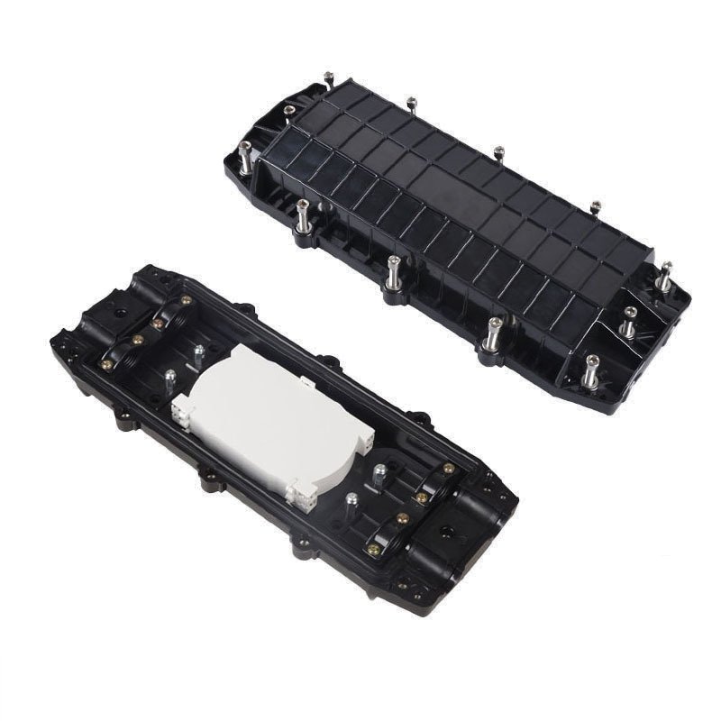
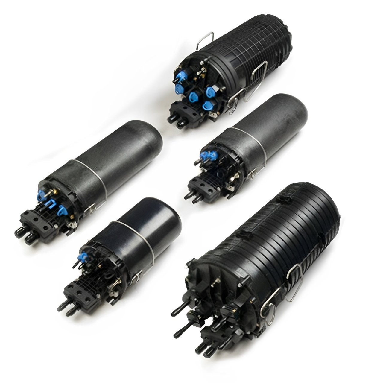
What Is a Fiber Joint Box?
A Fiber Joint Box (also called fiber closure, splice closure, or cable joint enclosure) is a sealed outdoor or underground enclosure designed to protect fiber optic cable splices from environmental hazards while providing mechanical strength and cable management.
Core Design and Purpose
The primary function of a Fiber Joint Box is to:
- Protect spliced fibers from water, dust, moisture, and UV radiation
- Provide mechanical protection against impact, crushing, and tension
- Organize and manage loose tubes, pigtails, and splice trays
- Allow future access for maintenance or additional splices
- Maintain the minimum bend radius of the fiber
Fiber Joint Box is typically used in outdoor environments — buried directly in the ground, mounted on poles, or installed in manholes. It is the workhorse of outside plant (OSP) fiber networks.
Key Construction Features
- High-impact, UV-stabilized plastic (usually PP or HDPE) or stainless steel
- IP68 or IP67 rating for waterproof and dustproof performance
- Multiple cable entry ports with heat-shrink or mechanical seals
- Stackable splice trays (typically 12–24 fibers per tray)
- Mounting brackets for wall, pole, or underground installation
- Pressure testing valve for verifying seal integrity
Commmesh Fiber Joint Box series is designed with patented sealing systems that maintain IP68 performance even after multiple re-openings, making them ideal for FTTH distribution networks and long-haul backbone projects.
What Are Fibre Optic Enclosures?
Fibre Optic Enclosures (also called fiber distribution enclosures, FDE, or fiber termination enclosures) are indoor or sheltered outdoor cabinets designed primarily for fiber termination, patching, and distribution rather than raw splicing.
Core Design and Purpose
Fibre Optic Enclosures focus on:
- Providing a secure, organized environment for fiber patching and cross-connects
- Housing adapters, pigtails, and patch cords
- Managing slack fiber and maintaining bend radius
- Allowing easy access for technicians to make changes
- Supporting high-density patching in data centers or central offices
Unlike Fiber Joint Box, which is usually buried or pole-mounted and sealed for long-term protection, Fibre Optic Enclosures are typically wall-mounted, rack-mounted, or floor-standing units used in controlled environments.
Key Construction Features
- Sheet metal or high-grade plastic construction
- IP54 to IP65 rating (suitable for indoor or sheltered outdoor use)
- High-density adapter panels (SC, LC, MPO)
- Cable management rings and slack storage
- Lockable doors for security
- Modular design for scalability
Commmesh offers a full range of Fibre Optic Enclosures from 1U to 6U rack-mount and wall-mount versions, optimized for both FTTH ODF applications and data center high-density environments.
What Is a Fiber Splicing Box?
Fiber Splicing Box is a smaller, more specialized enclosure focused primarily on housing and protecting fiber splices in a compact form factor. It is often used for smaller-scale or indoor applications.
Core Design and Purpose
Fiber Splicing Box is designed for:
- Protecting a limited number of splices (typically 12–48 fibers)
- Providing a compact, cost-effective solution for distribution points
- Easy access for splicing and re-splicing
- Use in indoor or semi-protected outdoor locations
It is generally smaller and lighter than a full Fiber Joint Box and is commonly used in FTTH distribution boxes, building entrance facilities, or as part of larger enclosures.
Key Construction Features
- Compact size, usually wall-mount or pole-mount
- IP55 to IP65 rating
- 1–4 splice trays
- Simple mechanical or heat-shrink sealing
- Cost-effective plastic construction
Commmesh Fiber Splicing Box series is popular for last-mile FTTH deployments where a full joint box is oversized for the number of fibers being spliced.
Head-to-Head Comparison: Fiber Joint Box vs Fibre Optic Enclosures vs Fiber Splicing Box
1. Primary Purpose and Application Environment
- Fiber Joint Box: Outdoor, buried or aerial, long-term protection of splices in the outside plant network.
- Fibre Optic Enclosures: Indoor or sheltered, focused on patching, distribution, and cross-connect in controlled environments.
- Fiber Splicing Box: Indoor or semi-outdoor, compact splicing solution for smaller fiber counts.
2. Protection Level and Sealing
- Fiber Joint Box: Highest protection (IP68), designed for direct burial and harsh environments.
- Fibre Optic Enclosures: Medium protection (IP54–IP65), suitable for indoor or weather-protected locations.
- Fiber Splicing Box: Medium protection (IP55–IP65), for semi-protected areas.
3. Fiber Capacity and Scalability
- Fiber Joint Box: High capacity (up to 576 fibers or more), highly scalable.
- Fibre Optic Enclosures: Medium to high capacity (48–576 fibers), excellent for patching.
- Fiber Splicing Box: Low to medium capacity (12–96 fibers), best for small distribution points.
4. Installation Location and Method
- Fiber Joint Box: Underground, pole-mounted, or manhole installation.
- Fibre Optic Enclosures: Rack-mounted, wall-mounted, or floor-standing in equipment rooms.
- Fiber Splicing Box: Wall-mounted or inside larger enclosures.
5. Cost Comparison (2026 China Market)
- Fiber Joint Box: $45–$180 per unit (depending on capacity)
- Fibre Optic Enclosures: $35–$220 per unit
- Fiber Splicing Box: $18–$65 per unit
6. Maintenance and Re-Entry
- Fiber Joint Box: Designed for infrequent re-entry, robust sealing.
- Fibre Optic Enclosures: Frequent access for patching, easy re-entry.
- Fiber Splicing Box: Moderate access, simple re-entry.

When to Choose Fiber Joint Box
Memilih Fiber Joint Box when:
- You need long-term protection for splices in outdoor, buried, or aerial environments.
- High fiber counts (96–576+) are being spliced at one location.
- The closure must withstand direct burial, flooding, or extreme weather.
- Future cable additions or maintenance access is required but not frequent.
Commmesh Fiber Joint Box series is widely used in backbone and distribution networks due to its proven IP68 sealing performance and robust mechanical design.
When to Choose Fibre Optic Enclosures
Memilih Fibre Optic Enclosures when:
- The primary need is high-density patching and cross-connect in indoor or equipment room environments.
- Technicians need frequent, easy access to make changes to connections.
- The enclosure will be rack-mounted or wall-mounted in a controlled environment.
- You need to manage patch cords, adapters, and slack fiber efficiently.
Commmesh Fibre Optic Enclosures are popular in FTTH ODF rooms, data centers, and central offices for their modularity and high port density.
When to Choose Fiber Splicing Box
Memilih Fiber Splicing Box when:
- You have a small number of fibers (12–96) to splice at a distribution point.
- Cost is a major consideration and full joint box capacity is not required.
- The location is semi-protected (inside a building entrance or secondary closure).
- You need a compact, lightweight solution for quick installation.
Commmesh Fiber Splicing Box series offers excellent value for last-mile FTTH distribution points and building entrance facilities.
Technical Comparison Table
| Fitur | Fiber Joint Box | Fibre Optic Enclosures | Fiber Splicing Box |
|---|---|---|---|
| Primary Environment | Outdoor / Buried / Aerial | Indoor / Equipment Room | Indoor / Semi-Outdoor |
| Protection Rating | Tingkat IP68 | IP54–IP65 | IP55–IP65 |
| Typical Fiber Capacity | 96–576+ | 48–576 | 12–96 |
| Access Frequency | Rendah | Tinggi | Medium |
| Main Function | Splice protection | Patching & distribution | Small-scale splicing |
| Cost per Unit (2026) | $45–$180 | $35–$220 | $18–$65 |
| Skalabilitas | Tinggi | Tinggi | Medium |
| Automation Compatibility | Medium | Tinggi | Rendah |
How to Choose the Right Solution for Your Project
Decision Framework
- Location and Environment
- Outdoor / buried → Fiber Joint Box
- Indoor / rack-mounted → Fibre Optic Enclosures
- Small distribution point → Fiber Splicing Box
- Jumlah Serat
- High count → Fiber Joint Box or high-capacity Enclosure
- Low count → Fiber Splicing Box
- Access Frequency
- Frequent patching → Fibre Optic Enclosures
- Rare access → Fiber Joint Box
- Budget and Timeline
- Cost-sensitive small project → Fiber Splicing Box
- Long-term backbone → Fiber Joint Box
Commmesh technical team provides free consultation to help you select the optimal combination of these three products for your network architecture.
Installation Best Practices for Each Type
Fiber Joint Box Installation
- Proper cable preparation and sealing
- Correct splice tray organization
- Pressure testing after closure
- Secure mounting for pole or underground use
Fibre Optic Enclosures Installation
- Rack or wall mounting with proper grounding
- Cable management and bend radius control
- Patch cord routing and labeling
Fiber Splicing Box Installation
- Compact mounting in distribution boxes
- Simple mechanical sealing
- Clear labeling for future maintenance
Maintenance and Longevity Considerations
All three products require different maintenance approaches:
- Fiber Joint Box: Infrequent but thorough re-entry checks
- Fibre Optic Enclosures: Regular cleaning and patch cord management
- Fiber Splicing Box: Occasional inspection of seals and splices
Dekam-Serat and Commmesh products are designed for long service life with minimal maintenance when installed correctly.
Conclusion: Choosing the Right Fiber Protection Solution
Fiber Joint Box, Fibre Optic Enclosures, Dan Fiber Splicing Box each serve distinct but complementary roles in modern fiber optic networks. Understanding their differences is essential for designing efficient, reliable, and cost-effective fiber infrastructure.
At Commmesh, we offer a complete range of high-quality fiber protection solutions, including Fiber Joint Box, Fibre Optic Enclosures, Dan Fiber Splicing Box, all manufactured to the highest international standards and backed by technical support.
Need help selecting the right solution for your next project? Contact the Commmesh team today. Our experts will provide free technical consultation, detailed product recommendations, and competitive quotations tailored to your specific network requirements.
Build your fiber network with confidence — choose Commmesh for reliable, high-performance fiber protection solutions.
]]>This is not a typical cyclical fluctuation. The current fiber optic price explosion is primarily driven by a sudden, massive, and sustained spike in demand caused by the widespread military use of fiber-guided kamikaze drones (loitering munitions) and advanced FPV (First Person View) drones in ongoing conflicts, particularly in Eastern Europe and the Middle East. These drones require large quantities of specialized optical fiber for real-time guidance, high-bandwidth video transmission, and jam-proof data links — a demand that has overwhelmed the global fiber supply chain and created direct competition with civilian telecom and data center projects.
In this comprehensive analysis from Commmesh, we examine the root causes of the 2025–2026 fiber price surge in detail, the specific role of drone warfare, why G.657A1 and G.657A2 grades are hit hardest, the supply-side bottlenecks that amplified the crisis, secondary effects on the broader fiber ecosystem, and what network operators, cable manufacturers, FTTH deployers, and data center builders should do to navigate this challenging period.
The Scale of the Current Fiber Optic Price Surge
To understand how unusual this situation is, let’s look at the numbers with context.
- G.652D (standard single-mode fiber): Prices have risen 45–70% since Q3 2025.
- G.657A1 (common bend-insensitive fiber for FTTH drops): Now trading at $22/km, up from $12–14/km in mid-2025 (an increase of approximately 80%).
- G.657A2 (enhanced bend performance for tight spaces and high-density applications): Currently at $35/km, up from $18–22/km just six months ago (an increase of approximately 90%).
These increases are not limited to raw fiber. Kabel pra-terminasi, micro cables designed for air-blowing, armored outdoor cables, and even patch cords have seen similar or steeper rises. Lead times, which were already stretched in 2025, have now extended from 4–6 weeks to 12–20 weeks for many popular grades, with some specialty fibers facing 6-month backlogs.
The price shock is being felt across the entire fiber ecosystem:
- Major telecom operators rolling out FTTH networks have had to revise budgets upward or delay projects.
- Hyperscale data center builders expanding 400G/800G/1.6T interconnects are facing higher CAPEX.
- 5G backhaul and fronthaul projects relying on bend-insensitive fiber are experiencing cost overruns.
- Cable manufacturers are squeezed between rising raw material costs and pressure from customers to keep prices stable.
This is the most significant fiber price event since the 2008–2009 financial crisis and the subsequent recovery period.
Primary Cause: Explosive Military Demand from Drone Warfare
The single biggest driver behind the current fiber price surge is the massive and sustained demand for optical fiber in military drone systems, especially fiber-guided kamikaze/loitering munitions and advanced FPV drones.
Why Modern Military Drones Need So Much Optical Fiber
Unlike radio-controlled drones that can be jammed, spoofed, or intercepted by electronic warfare systems, fiber-guided drones use a thin optical fiber as the primary data link between the ground control station and the munition. This provides:
- Extremely high bandwidth for real-time 4K or even 8K video transmission
- Near-zero latency (critical for precision targeting)
- Complete immunity to radio frequency jamming and interception
- Secure, un-hackable communication channel
A single fiber-guided kamikaze drone can consume 300 to 2,500 meters of specialized optical fiber per mission, depending on range and operational profile. When military forces launch hundreds or even thousands of such drones per week — as documented in the ongoing conflicts in Ukraine and the Middle East — the cumulative fiber consumption becomes enormous.
Scale of the Demand Shock
Industry sources and supply chain intelligence estimate that drone-related fiber demand in Q4 2025 alone reached 150,000–250,000 kilometers per month — roughly equivalent to the entire annual fiber consumption of a mid-sized European country’s national FTTH rollout program. This demand is heavily concentrated on G.657A1 and G.657A2 bend-insensitive fibers, because drone spools require extreme flexibility, tight coiling capability, and very low bend-induced attenuation.
The result is a classic textbook supply-demand imbalance: civilian demand from telecom operators, data centers, and 5G projects continues at record levels, while military procurement has suddenly absorbed 25–45% of global high-performance fiber production capacity, depending on the grade.
This military demand is not a one-off spike. It has become sustained and structural as both sides in ongoing conflicts have scaled up drone production and usage, creating a new baseline level of fiber consumption that did not exist before late 2025.
Why G.657A1 and G.657A2 Grades Are Hit Hardest
Not all fiber types are affected equally. The price surge is most severe for bend-insensitive single-mode fibers:
- G.657A1: Now $22/km (up ~80% from mid-2025)
- G.657A2: Now $35/km (up ~90% from mid-2025)
Technical Reasons for the Concentration
These fibers are specifically engineered for superior bend performance (minimum bend radius as low as 5–7.5 mm with very low additional attenuation). This makes them ideal for:
- Drone fiber spools (must be coiled tightly on small reels without signal degradation)
- FTTH drop cables in dense urban environments with tight corners
- Data center high-density patching and high-count cables
- 5G small cell and fronthaul deployments where space is constrained
Because drone manufacturers prioritize G.657 series fibers for their mechanical flexibility and optical reliability under extreme stress, civilian buyers are now competing directly with military procurement for the same limited production capacity. Standard G.652D has seen a milder increase (45–70%) because it is less suitable for drone applications due to higher bend-induced loss.
Supply-Side Constraints That Amplified the Crisis
The price surge is not driven by demand alone. Several supply-side bottlenecks have made the situation significantly worse:
1. Preform Production Bottleneck
Optical fiber starts with a high-purity glass preform. Global preform manufacturing capacity is concentrated among a relatively small number of major players (YOFC, Corning, Prysmian, Sumitomo, Fujikura, and a few others). Military orders have been given priority access to the highest-purity preforms needed for low-attenuation G.657 fibers, creating shortages for commercial fiber optic cable manufacturers.
2. Fiber Drawing Tower Capacity Limits
Even when preforms are available, the actual fiber drawing process (melting the preform at over 2,000°C and drawing it into thin fiber at high speed) has limited global capacity. Many drawing towers are already running at 95–100% utilization. Building new drawing towers is capital-intensive and takes 12–18 months from decision to production.
3. Specialty Coating and Jacketing Constraints
G.657A1 and G.657A2 require advanced low-friction and high-strength coatings. Specialty chemical suppliers for these coatings have struggled to scale production fast enough, creating additional bottlenecks.
4. Geopolitical and Logistics Factors
Export restrictions on certain raw materials, shipping disruptions in key regions, and higher energy costs for glass melting have added further upward pressure on prices.
Secondary Market Effects and Broader Industry Impact
The fiber price surge is rippling through the entire fiber optic ecosystem with significant consequences:
- FTTH Operators: Many planned rollouts have been delayed or scaled back. Some smaller projects in emerging markets have been postponed indefinitely due to cost overruns.
- Data Center Builders: Hyperscalers expanding 400G/800G/1.6T interconnects are facing higher CAPEX, forcing some projects to be re-phased.
- 5G Deployers: Backhaul and fronthaul projects relying on bend-insensitive fiber are experiencing budget pressure, slowing small cell deployment in some regions.
- Cable Manufacturers: Squeezed margins have forced many to pass on price increases to customers, leading to a ripple effect on end-user pricing for patch cords, pre-terminated cables, and ODN components.
- End Users: Residential broadband providers and enterprise customers may eventually see higher service prices as costs are passed downstream.
Some smaller FTTH projects in Southeast Asia and Africa have already been postponed or redesigned to use more G.652D where bend performance is less critical.
How Long Will the Surge Last? Expert Forecasts for 2026–2027
Industry analysts, major fiber producers, and supply chain intelligence firms offer the following consensus outlook:
- Short term (Q1–Q2 2026): Prices are likely to remain high or even rise further as military demand continues and civilian restocking accelerates.
- Mid term (Q3–Q4 2026): Possible stabilization or modest easing if military procurement slows or new preform and drawing capacity comes online.
- Long term (2027 and beyond): Several major manufacturers announced new preform and drawing tower investments in late 2025. These are expected to ease pressure significantly by late 2027 or early 2028, assuming no new major conflicts emerge.
Commmesh is actively monitoring the situation daily and working with multiple global suppliers to secure stable fiber supply for our customers through this volatile period.
Strategic Recommendations for Network Operators and Cable Manufacturers
For FTTH and Telecom Operators
- Lock in long-term fiber supply contracts as soon as possible, even at current elevated prices, to secure volume and pricing stability.
- Consider hybrid cable designs that use more G.652D in less bend-critical sections of the network.
- Explore air-blowing micro cable solutions to reduce overall fiber consumption per project.
- Phase deployments intelligently, prioritizing high-ROI areas first.
For Cable Manufacturers
- Aggressively diversify preform suppliers and secure long-term agreements.
- Invest in higher-efficiency drawing processes and yield improvement technologies.
- Develop alternative fiber designs that reduce reliance on scarce G.657 grades where possible.
- Maintain strategic buffer stock of critical grades when market conditions allow.
For End Users and Project Planners
- Build fiber cost escalation clauses into new project contracts.
- Re-evaluate project budgets and timelines with current fiber pricing in mind.
- Consider leasing dark fiber or making greater use of existing infrastructure to stretch budgets.
How Commmesh Is Responding to the Fiber Price Surge
As a leading fiber optic cable manufacturer, Commmesh is taking proactive and transparent steps to support our customers during this challenging market:
- We have secured long-term preform supply agreements with multiple global suppliers to stabilize our own production.
- We have optimized production schedules to prioritize high-demand G.657 grades for FTTH and data center customers.
- We are developing cost-optimized cable designs that maintain required performance while reducing overall material usage.
- We offer flexible volume-based pricing stability programs and extended payment terms for strategic customers.
- We continue to provide full technical support for alternative deployment methods (air blowing, micro trenching, ribbon fiber) to help customers maximize the value of every kilometer of fiber.
We remain committed to delivering high-quality, reliable fiber optic solutions even in a highly volatile market environment.
Conclusion: Navigating the 2025–2026 Fiber Price Crisis
The dramatic surge in kabel serat optik prices from late 2025 into early 2026 is primarily driven by the explosive and sustained demand from military drone applications, particularly fiber-guided kamikaze and FPV drones. This sudden military consumption has collided with already tight commercial supply chains, pushing prices of critical bend-insensitive grades like G.657A1 to $22/km and G.657A2 to $35/km, with the possibility of further increases if demand pressure persists.
While the situation is challenging and painful for many projects, it is ultimately temporary. New preform and drawing capacity is being added globally, and the market will eventually rebalance. In the meantime, network operators, cable manufacturers, and project planners must adapt through smarter procurement strategies, optimized network designs, and more efficient deployment methods.
At Commmesh, we are here to help you navigate this difficult period with reliable supply, technical expertise, and cost-effective solutions. Whether you need standard G.652D, bend-insensitive G.657 fibers, air-blowing micro cables, or complete turnkey fiber deployment support, our team is ready to work with you to minimize the impact of current price volatility while securing the fiber you need for your critical network projects.
The fiber optic networks of tomorrow are being built today. Let’s build them smartly, efficiently, and resiliently together.
Contact Commmesh today to discuss your fiber requirements and explore strategies to mitigate the impact of the current market conditions.
]]>In 2026, with global FTTH connections exceeding 2.5 billion and 5G/6G networks demanding ultra-high fiber density, air blowing micro fiber optic cable has become the preferred deployment technology for both new builds and network upgrades. Its micro-duct compatibility, low installation friction, and scalability make it ideal for congested urban environments, long rural spans, and high-rise buildings where traditional pulling is impractical or too expensive.
At Commmesh, we specialize in manufacturing premium air blowing micro fiber optic cable solutions that meet or exceed international standards (ITU-T, IEC, Telcordia) while delivering exceptional blowing performance, low attenuation, and long-term reliability. This comprehensive guide explains everything you need to know about air blowing micro fiber optic cable — from the underlying technology and installation process to technical specifications, real-world applications, cost analysis, comparison with traditional methods, future trends, and practical buying considerations. By the end, you will have a complete understanding of why air blowing micro fiber optic cable is the smartest choice for modern fiber deployment projects.
What Is Air Blowing Micro Fiber Optic Cable?
Air blowing micro fiber optic cable (also called blown fiber cable, micro duct cable, or air-blown fiber) is a lightweight, high-fiber-count optical cable specifically engineered for installation using compressed air through pre-laid micro ducts. The cable is designed with a small outer diameter (typically 3–8 mm), low friction sheath, and high tensile strength to allow it to be “blown” hundreds or even thousands of meters through narrow micro ducts without damage.
Core Technical Concept
The technology relies on the principle of pneumatic transport: compressed air (usually 8–12 bar) creates a high-velocity airflow inside the micro duct. The micro cable, with its specially formulated low-friction outer jacket (often HDPE or special polymer with drag-reducing additives), rides this airflow like a bullet, propelled forward with minimal pulling force at the entry point.
Key Advantages Over Traditional Cable Pulling
- Smaller pathway required: Micro ducts are only 10–20 mm in diameter, versus 50–100 mm for traditional conduits.
- Longer installation distances: Single blows of 1,000–2,500 meters are common; multi-section blowing can reach 5–10 km.
- Less manpower and equipment: One or two technicians plus a blowing machine replace large pulling crews and heavy winches.
- Future-proof scalability: Empty micro ducts can be installed first, then cables blown in as needed — ideal for phased FTTH rollouts.
- Lower total installed cost: 30–60% savings in labor, trenching, and conduit materials.
Commmesh air blowing micro fiber optic cable is optimized for these advantages, with precise diameter control, high blowing distance performance, and compatibility with all major micro duct systems on the market.
History and Evolution of Air Blowing Micro Fiber Optic Cable Technology
The concept of blowing fiber through ducts dates back to the late 1980s in Europe, but commercial viability emerged in the early 2000s with the development of micro ducts and low-friction cable jackets.
Early Development (1980s–2000s)
- 1987–1995: First experiments in the UK and Netherlands using compressed air to install lightweight fiber bundles.
- 2000–2005: Introduction of micro ducts (10–20 mm) and the first commercial blown fiber systems by companies like Emtelle and Prysmian.
Mainstream Adoption (2010–2020)
- 2010: ITU-T and IEC standards begin recognizing air-blown fiber.
- 2015–2020: Massive FTTH rollouts in Europe, Asia, and North America adopt air blowing for urban and suburban networks.
2026 State-of-the-Art
Today, air blowing micro fiber optic cable supports fiber counts up to 432 or more in a single 8–10 mm cable, with blowing distances exceeding 2,500 meters in straight runs. Materials have evolved to include nano-engineered low-friction coatings and high-strength aramid strength members, enabling installation in previously impossible pathways.
Commmesh has been at the forefront of this evolution, developing proprietary jacket compounds that achieve record blowing distances while maintaining excellent mechanical protection.
How Air Blowing Micro Fiber Optic Cable Works: The Physics and Process
Understanding the physics behind air blowing micro fiber optic cable installation is key to appreciating its advantages.
The Fundamental Physics
Compressed air inside the micro duct creates a high-velocity airflow (typically 20–40 m/s). The micro cable experiences two main forces:
- Drag force from air flow pushing the cable forward
- Friction force between cable jacket and duct wall (minimized by special low-friction coatings)
The net result is that the cable “floats” on an air cushion, requiring very little pulling force at the entry point (usually 5–15 kg).
Step-by-Step Installation Process
- Micro Duct Pre-Installation Micro ducts (PE or PVC, 10–20 mm ID) are laid in trenches, existing conduits, or aerial routes.
- Persiapan Kabel Itu air blowing micro fiber optic cable is loaded into the blowing machine with a blowing head that seals the duct and injects air.
- Air Blowing Compressor supplies 8–12 bar air. The machine feeds the cable while maintaining optimal air flow.
- Monitoring Real-time monitoring of air pressure, cable speed, and tension ensures safe installation.
- Penghentian Cable is pulled out at the far end and terminated into splice closures or distribution boxes.
Commmesh air blowing micro fiber optic cable is specifically engineered with a low-friction coefficient (<0.15) and optimized stiffness to achieve the longest possible blowing distances.
Technical Specifications and International Standards for Air Blowing Micro Fiber Optic Cable
Fiber Types and Counts
- Single-mode (G.652D, G.657A1/A2/B3 bend-insensitive)
- Multimode (OM3, OM4, OM5)
- Fiber counts: 2–432 fibers (ribbon or loose tube)
Konstruksi Kabel
- Central loose tube or ribbon structure
- Water-blocking yarns or gel
- Low-friction outer sheath (HDPE with special additives)
- Aramid or fiberglass strength members
- Outer diameter: 3–10 mm depending on fiber count
Key Performance Parameters
- Blowing distance: 1,000–2,500+ meters in straight micro duct
- Installation tension: <500 N
- Crush resistance: >1,000 N/100 mm
- Operating temperature: -40°C to +70°C
- Attenuation: ≤0.19 dB/km @1550 nm (single-mode)
Commmesh products meet or exceed:
- ITU-T L.100 / L.101
- IEC 60794-1-21
- Telcordia GR-20
- RoHS and REACH
Types of Air Blowing Micro Fiber Optic Cable
Loose Tube Air Blown Cable
Most common type for long-distance blowing. Fibers are in gel-filled loose tubes for maximum protection.
Ribbon Air Blown Cable
High fiber count in flat ribbon form for faster splicing and higher density.
Micro Bundle Air Blown Cable
Multiple small sub-bundles inside one outer jacket — ideal for phased deployment.
Direct Buried / Aerial Variants
Specialized jackets for outdoor use (UV-resistant, rodent-proof, or figure-8 messenger).
Commmesh offers all variants with custom fiber counts and jacket colors for easy identification during installation.
Advantages of Air Blowing Micro Fiber Optic Cable Over Traditional Pulling Methods
1. Dramatically Reduced Installation Time
Traditional pulling can take days per section. Air blowing often completes the same distance in hours.
2. Lower Labor and Equipment Costs
One blowing machine + 2–3 technicians vs. large pulling crews and heavy winches.
3. Smaller Trenching and Conduit Requirements
Micro ducts require 50–70% less excavation volume.
4. Future-Proof Network Design
Install empty micro ducts first, then blow in cables as demand grows — ideal for FTTH brownfield upgrades.
5. Lower Risk of Cable Damage
No high pulling tension — fiber stress is minimized.
6. Environmental Benefits
Less disruption to roads, gardens, and existing infrastructure.
Commmesh air blowing micro fiber optic cable maximizes all these advantages through optimized design.
Micro Duct Systems for Air Blowing Micro Fiber Optic Cable
The micro duct is as important as the cable itself.
Types of Micro Ducts
- Single micro duct (10–20 mm)
- Multi-duct bundles (pre-connected 7/12/19-way)
- Direct buried micro duct
- Aerial micro duct with messenger
Material and Performance
- HDPE with low friction inner layer
- Anti-static and anti-rodent options
- Pressure rating 8–15 bar
Commmesh supplies complete micro duct + cable solutions that are pre-tested for optimal blowing performance.
Detailed Installation Process for Air Blowing Micro Fiber Optic Cable
Pre-Installation Preparation
- Duct integrity testing (air pressure and mandrel test)
- Lubricant application (if required)
- Cable end preparation and blowing head attachment
Blowing Operation
- Compressor setup and pressure regulation
- Cable feeding speed control
- Real-time monitoring of tension and air flow
Post-Blowing Termination
- Cable pulling out at far end
- Splicing or connectorization
- Pressure testing of the installed section
Commmesh provides detailed installation manuals, training, and on-site support for all projects.
Applications of Air Blowing Micro Fiber Optic Cable in 2026
FTTH Last-Mile Deployment
The #1 application — blowing micro cables through existing or new micro ducts in urban and suburban areas.
5G Backhaul and Fronthaul
High-fiber-count micro cables blown between cell towers and baseband units.
Data Center Interconnects
Intra-building and campus micro duct networks for high-speed 400G/800G links.
Rural Broadband
Long-distance blowing (2–5 km) through existing conduits or direct-buried micro ducts.
Smart City and IoT Networks
Micro cable networks for surveillance cameras, traffic sensors, and 5G small cells.
Commmesh cables are optimized for all these applications with custom fiber counts and jacket designs.
Cost Analysis and ROI of Air Blowing Micro Fiber Optic Cable Projects
Typical Project Cost Breakdown (per km, 2026 China market)
- Micro duct installation: 8,000–15,000 RMB/km
- Air blowing micro fiber optic cable: 12,000–28,000 RMB/km (depending on fiber count)
- Blowing equipment rental/labor: 3,000–6,000 RMB/km
- Termination and testing: 2,000–4,000 RMB/km
Total installed cost: 25,000–53,000 RMB/km
ROI Advantages
- 40–60% lower civil works cost vs traditional pulling
- 50–70% faster deployment
- Reduced labor and equipment rental
- Future cable upgrades without new trenching
Typical payback period for air blowing projects is 1–3 years compared to traditional methods.
Maintenance and Troubleshooting of Air Blowing Micro Fiber Optic Cable
Routine Maintenance
- Periodic duct pressure testing
- Visual inspection of termination points
- Cleaning of micro ducts if contamination occurs
Common Issues and Solutions
- Cable stuck during blowing → use lubricant or reverse air flow
- High attenuation → check for duct kinks or excessive bends
- Fiber break → use OTDR to locate and repair
Commmesh cables include water-blocking and high-strength members that minimize long-term maintenance needs.
Comparison with Traditional Cable Pulling Methods
Traditional Pulling
- High pulling tension (up to 2,700 N)
- Large conduits required
- High risk of fiber damage
- Slow installation
Air Blowing Micro Fiber Optic Cable
- Low tension (<500 N)
- Micro ducts only
- Minimal fiber stress
- Fast installation
Air blowing is clearly superior for most modern deployments.
Future Trends in Air Blowing Micro Fiber Optic Cable Technology
- Higher fiber counts (up to 864+ fibers in 10 mm cable)
- New low-friction nano-coatings
- Integrated power + fiber hybrid micro cables
- AI-assisted blowing machines with real-time optimization
- Sustainable bio-based sheath materials
Commmesh is already developing next-generation products in these areas.
How to Choose the Right Air Blowing Micro Fiber Optic Cable Supplier
Key criteria:
- Proven blowing distance performance
- Full compliance with ITU-T, IEC, and Telcordia standards
- Customization capability (fiber count, jacket color, special coatings)
- Technical support and installation training
- Long-term warranty and local spare parts availability
Commmesh meets all these criteria with industry-leading blowing performance and full technical support.
Conclusion: Why Air Blowing Micro Fiber Optic Cable Is the Future of Fiber Deployment
Air blowing micro fiber optic cable offers unmatched installation speed, lower costs, future-proof scalability, and minimal disruption compared to traditional methods. In 2026, it has become the default choice for new FTTH, 5G, and high-density fiber projects worldwide.
At Commmesh, we manufacture premium air blowing micro fiber optic cable solutions that deliver record blowing distances, low attenuation, and long-term reliability. Our complete micro duct + cable systems are used by leading operators across China and Asia.
Ready to upgrade your fiber deployment strategy? Contact the Commmesh team today for technical specifications, blowing performance data, custom quotes, and on-site installation support.
Memilih air blowing micro fiber optic cable — the smarter, faster, and more cost-effective way to build future-ready fiber networks.
]]>In the rapidly evolving world of telecommunications and data transmission, two technologies stand out for their transformative impact: Fiber Optic and Dense Wavelength Division Multiplexing (DWDM). Both play critical roles in enabling high-speed, reliable, and scalable internet connectivity. However, understanding the differences and synergies in the comparison of Fiber Optic vs. DWDM is essential for businesses, IT professionals, and network engineers looking to optimize their infrastructure. This comprehensive guide dives deep into the intricacies of these technologies, exploring their functionalities, advantages, limitations, and how they complement each other in modern networks.
Whether you’re building a new network or upgrading an existing one, knowing the nuances of Fiber Optic and DWDM can help you make informed decisions. Let’s explore these technologies in detail to uncover their unique contributions to the digital landscape.
What is Fiber Optic Technology?
Basics of Fiber Optic Communication
Fiber Optic technology refers to the transmission of data as light pulses through thin strands of glass or plastic fibers. Unlike traditional copper cables, which transmit electrical signals, fiber optics use light to carry information over long distances with minimal loss. This technology forms the backbone of modern internet and telecommunication systems due to its ability to handle vast amounts of data at incredible speeds.
The core principle behind Fiber Optic communication is total internal reflection, where light signals bounce within the fiber core without escaping, ensuring efficient data transfer. Fiber Optic cables are immune to electromagnetic interference, making them ideal for environments with high electrical noise.
Advantages of Fiber Optic Technology
- Bandwidth Tinggi: Fiber Optic cables support significantly higher data rates compared to copper cables, making them perfect for bandwidth-intensive applications.
- Long-Distance Transmission: Signals can travel over 100 kilometers without needing regeneration, reducing infrastructure costs.
- Immunity to Interference: Unlike copper, Fiber Optic is unaffected by electromagnetic interference, ensuring reliable performance.
- Security: Tapping into a Fiber Optic cable is difficult, providing an added layer of data security.
Limitations of Fiber Optic Technology
- Installation Cost: Initial setup and deployment of Fiber Optic cables can be expensive due to the need for specialized equipment and skilled labor.
- Kerapuhan: Fiber Optic cables are more delicate than copper cables and can be damaged if not handled properly.
What is DWDM Technology?
Understanding Dense Wavelength Division Multiplexing
Dense Wavelength Division Multiplexing (DWDM) is an advanced optical networking technology that increases the capacity of Fiber Optic cables by multiplexing multiple wavelengths of light onto a single fiber. Essentially, DWDM allows multiple data streams to travel simultaneously over the same fiber by assigning each stream a unique wavelength. This technology is a game-changer for network providers looking to maximize the potential of their existing Fiber Optic infrastructure.
DWDM operates by combining and separating optical signals at different wavelengths, enabling data rates of terabits per second over long distances. It is widely used in backbone networks, metropolitan area networks (MANs), and data centers where high-capacity transmission is critical.
Advantages of DWDM Technology
- Increased Capacity: DWDM can support dozens of channels on a single fiber, dramatically increasing data throughput without the need for additional cables.
- Cost-Effectiveness: By utilizing existing Fiber Optic infrastructure, DWDM reduces the need for laying new cables, saving significant costs.
- Scalability: DWDM systems can be upgraded to support more channels as demand grows, offering future-proofing for networks.
- Long-Haul Capability: DWDM is optimized for long-distance transmission with minimal signal degradation.
Limitations of DWDM Technology
- Complex Implementation: DWDM systems require precise equipment and expertise for installation and maintenance, which can be costly.
- Dependence on Fiber Optic: DWDM cannot function without a robust Fiber Optic infrastructure, meaning it is not a standalone solution.
Fiber Optic vs. DWDM: Key Differences and Synergies
Core Comparison of Technologies
When discussing Fiber Optic vs. DWDM, it’s important to note that these are not entirely competing technologies but rather complementary ones. Fiber Optic refers to the physical medium through which data is transmitted as light, while DWDM is a technique to enhance the capacity of that medium by multiplexing multiple signals. In essence, DWDM builds upon Fiber Optic technology to meet the growing demand for bandwidth.
To provide a clearer understanding, let’s compare the two technologies across several key parameters in the table below:
| Parameter | Fiber Optic | DWDM |
|---|---|---|
| Definition | A physical medium for data transmission using light pulses through glass or plastic fibers. | A multiplexing technology that increases Fiber Optic capacity by transmitting multiple wavelengths on a single fiber. |
| Purpose | Provides the infrastructure for high-speed data transmission. | Enhances the capacity and efficiency of Fiber Optic cables. |
| Lebar pita | High, but limited to a single data stream per fiber without multiplexing. | Extremely high, as it supports multiple data streams on a single fiber. |
| Biaya | High initial installation cost for cables and equipment. | Additional cost for DWDM equipment, but saves on new fiber installation. |
| Skalabilitas | Limited unless paired with technologies like DWDM. | Highly scalable with the ability to add more wavelengths as needed. |
| Aplikasi | Used in internet backbones, LANs, and WANs. | Primarily used in long-haul networks and data centers for high-capacity needs. |
How Fiber Optic and DWDM Work Together
In the context of Fiber Optic vs. DWDM, it’s critical to understand their interdependence. DWDM relies on Fiber Optic cables as its foundation; without the physical medium of fiber, DWDM technology cannot operate. On the other hand, Fiber Optic cables alone may not suffice for modern data demands without the capacity-boosting capabilities of DWDM. Together, they create a powerful solution for high-speed, high-capacity data transmission over vast distances.
For instance, internet service providers (ISPs) and large enterprises often deploy DWDM systems over their existing Fiber Optic networks to handle the exponential growth in data traffic driven by cloud computing, streaming services, and IoT devices. This synergy ensures that networks remain efficient and cost-effective while meeting future scalability needs.
Applications of Fiber Optic and DWDM in Modern Networks
Fiber Optic Applications
Fiber Optic technology is ubiquitous in today’s digital ecosystem. It is used in a wide range of applications, including:
- Internet Backbones: Fiber Optic cables form the core of global internet infrastructure, connecting continents through undersea cables.
- Local Area Networks (LANs): Many businesses use Fiber Optic for internal networks to ensure fast and reliable connectivity.
- Telecommunications: Fiber Optic supports voice, video, and data services for telecom providers.
- Medical and Industrial Uses: Fiber Optic is also used in medical imaging and industrial automation for its precision and reliability.
DWDM Applications
DWDM, as an enhancement to Fiber Optic, is primarily deployed in scenarios requiring massive data throughput. Its applications include:
- Jaringan Jarak Jauh: DWDM is essential for transmitting data across countries and continents without signal loss.
- Pusat Data: Large-scale data centers use DWDM to manage high volumes of inter-data center traffic.
- Metropolitan Area Networks (MANs): DWDM connects multiple locations within a city, supporting high-bandwidth services like video conferencing and cloud computing.
- 5G Infrastructure: The rollout of 5G networks relies on DWDM to handle the increased data demands of mobile connectivity.
Future Trends in Fiber Optic and DWDM Technologies
Advancements in Fiber Optic
The future of Fiber Optic technology looks promising with ongoing research into new types of fibers, such as multi-core and hollow-core fibers, which promise even higher data rates and lower latency. Additionally, innovations in installation techniques are reducing costs, making Fiber Optic more accessible for rural and underserved areas. As the demand for internet connectivity continues to soar, Fiber Optic will remain the cornerstone of global communication networks.
Evolution of DWDM
DWDM technology is also evolving rapidly, with newer systems supporting even more wavelengths and higher data rates per channel. The integration of coherent DWDM systems, which use advanced modulation techniques, is pushing the boundaries of long-haul transmission. Furthermore, the adoption of software-defined networking (SDN) with DWDM allows for more flexible and efficient network management, ensuring that DWDM remains relevant in the era of dynamic, on-demand bandwidth.
Conclusion: Making the Right Choice for Your Network with Fiber Optic and DWDM
In the debate of Fiber Optic vs. DWDM, it’s clear that these technologies are not rivals but partners in delivering the high-speed, high-capacity networks that power our digital world. Fiber Optic provides the essential infrastructure for data transmission, while DWDM amplifies its potential by enabling multiple data streams over a single fiber. Together, they address the ever-growing demands of modern applications, from streaming and cloud computing to 5G and beyond.
Choosing between or combining these technologies depends on your specific needs, budget, and scalability goals. For businesses and network providers, investing in a robust Fiber Optic foundation with DWDM enhancements is often the most future-proof strategy. If you’re ready to optimize your network infrastructure, consult with a telecommunications expert to design a solution tailored to your requirements. Take the first step today—reach out to a professional to explore how Fiber Optic and DWDM can transform your connectivity and drive your business forward.
]]>As of 2026, FTTX has become the global standard for broadband infrastructure, with over 2.5 billion connections worldwide. Different FTTX types address diverse needs—from premium residential service to industrial automation, enterprise campuses, and 5G infrastructure.
This guide focuses exclusively on explaining every major FTTX type in depth: Jaringan FTTH (Fiber to the Home), FTTB (Fiber to the Building), FTTC (Fiber to the Curb), FTTN (Fiber to the Node), Bahasa Indonesia: FTTP (Fiber to the Premises), FTTD (Fiber to the Desktop), FTTE (Fiber to the Telecom Enclosure), FTTA (Fiber to the Antenna), FTTR (Fiber to the Room), FTTM (Fiber to the Machine), FTTF (Fiber to the Floor), and FTTZ (Fiber to the Zone). Each type is examined with its definition, architecture, technical characteristics, advantages, disadvantages, and comparisons to other variants.
1. FTTH (Fiber to the Home): The Gold Standard of FTTX
Jaringan FTTH (Fiber to the Home) is the most advanced FTTX architecture, where optical fiber runs directly from the service provider’s central office or headend to the individual residence, providing a dedicated fiber connection to each home.
Architecture of FTTH
FTTH typically uses Passive Optical Network (PON) technology:
- Terminal Jalur Optik (OLT): Located in the central office, serving as the starting point.
- Feeder Fiber: High-count cable from OLT to a passive splitter.
- Optical Splitter: Usually a 1×32 atau 1×64 PLC splitter in a closure or cabinet, dividing the signal.
- Distribution Fiber: Single-fiber cables to neighborhood nodes.
- Drop Fiber: Final cable to the home’s termination box.
- Terminal Jaringan Optik (ONT): Inside the home, converting optical signals to electrical for devices.
Point-to-Point (P2P) FTTH uses dedicated fiber per home without splitting.
Technical Characteristics
- Jarak: Up to 20–40 km from OLT (PON).
- Kecepatan: GPON (2.5 Gbps down/1.25 up), XGS-PON (10 Gbps symmetric), 50G-PON (50 Gbps).
- Split Ratio: 1:32 to 1:64 (higher ratios possible with advanced PON).
- Latency: <1 ms.
- Lebar pita: Symmetric gigabit+ per home.
Advantages of FTTH
- Highest possible bandwidth and symmetry.
- Lowest latency, ideal for gaming, VR, and real-time applications.
- Immune to electromagnetic interference.
- Future-proof for 100G+ speeds.
- Dedicated fiber ensures consistent performance regardless of neighbors.
Disadvantages of FTTH
- Highest installation cost due to running fiber to each home.
- Time-consuming deployment (trenching or aerial work per residence).
- Requires skilled technicians for splicing/termination.
Comparison with Other FTTX Types
FTTH outperforms FTTB/FTTC/FTTN in speed and reliability but at higher cost. It is the preferred choice for new greenfield deployments where long-term performance justifies investment.
Jaringan FTTH is dominant in leading markets like China, South Korea, and Singapore, and accelerating in Europe and North America.
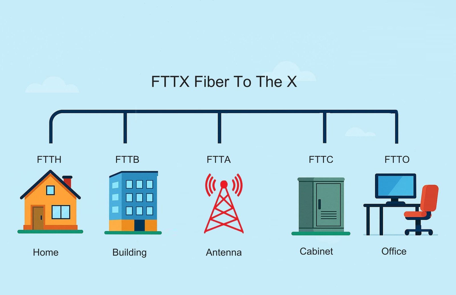
2. FTTB (Fiber to the Building): Efficient for Multi-Dwelling Units
FTTB (Fiber to the Building) brings optical fiber to the building’s basement, utility room, or telecommunications closet, with the final distribution to individual units handled by copper twisted pair (VDSL) or Ethernet cables.
Architecture of FTTB
- Feeder Fiber: From central office to building ODF or termination point.
- Building Distribution: VDSL2 DSLAM or Ethernet switch in basement.
- In-Building Wiring: Existing copper telephone lines or Cat5/6 Ethernet to apartments.
PON can be used up to the building, with active equipment for vertical distribution.
Technical Characteristics
- Jarak: Fiber to building; copper last 50–200 m.
- Kecepatan: Up to 1 Gbps per unit with VDSL2+ or Ethernet.
- Split Ratio: Higher possible (1:128+).
- Latency: Slightly higher than FTTH due to copper segment.
Advantages of FTTB
- Significantly lower cost than FTTH for multi-dwelling units (MDUs).
- Faster deployment using existing in-building copper.
- Good performance for apartments and offices.
- Scalable for dense urban environments.
Disadvantages of FTTB
- Copper segment limits maximum speed and symmetry.
- Performance degrades with longer copper runs.
- Higher latency than pure fiber solutions.
Comparison with Other FTTX Types
FTTB is a cost-effective compromise between FTTH (full fiber) and FTTC/FTTN (more copper). It is widely used in high-rise apartments where running fiber to each unit is impractical.
FTTB is common in Europe and urban Asia for retrofitting older buildings.
3. FTTC (Fiber to the Curb) and FTTN (Fiber to the Node): Transitional Architectures
FTTC (Fiber to the Curb) and FTTN (Fiber to the Node) are similar architectures that extend fiber closer to homes than traditional DSL but stop short of the premises.
Architecture of FTTC
- Fiber to Curb Cabinet: Located 100–300 m from homes, containing DSLAM.
- Copper Drop: VDSL2 lines to individual homes.
Architecture of FTTN
- Fiber to Node: Larger cabinet serving 300–1000 m radius.
- Longer Copper Loops: Existing telephone lines.
FTTN is essentially FTTC with larger service area.
Technical Characteristics
- Jarak: Copper last 100–1000 m.
- Kecepatan: FTTC: 100–500 Mbps; FTTN: 50–100 Mbps.
- Latency: Higher due to copper.
- Teknologi: VDSL2 or G.fast.
Keuntungan
- Lowest fiber deployment cost.
- Quick upgrade from existing DSL.
- Uses legacy copper infrastructure.
Disadvantages
- Performance degrades significantly with distance.
- Asymmetric speeds.
- Susceptible to interference.
Comparison with Other FTTX Types
FTTC/FTTN are transitional solutions, offering better performance than pure DSL but inferior to FTTH/FTTB. Many operators use them as stepping stones to full FTTH.
4. FTTP (Fiber to the Premises): The Commercial FTTX Variant
Bahasa Indonesia: FTTP (Fiber to the Premises) is a broad term for fiber delivery to any non-residential premises, such as offices, schools, hospitals, or factories.
Architecture
Similar to FTTH but scaled for commercial needs:
- Dedicated or shared fiber.
- Higher capacity ONTs or routers.
Technical Characteristics
- Speed: 1–10 Gbps+.
- Symmetry: Full symmetric.
Keuntungan
- Gigabit+ for business-critical applications.
- Reliable for VoIP, cloud, video conferencing.
Disadvantages
- Higher cost for commercial-grade equipment.
Comparison
FTTP overlaps with FTTH but emphasizes enterprise requirements like SLAs and redundancy.
5. Specialized FTTX Types: FTTD, FTTE, FTTA, FTTR, FTTM, and More
FTTD (Fiber to the Desktop)
FTTD extends fiber directly to individual workstations.
Architecture: Fiber from switch to desk media converter or ONT.
Advantages: Ultra-low latency, 10 Gbps+ to desk, EMI immunity.
Disadvantages: High cost, complex installation.
Applications: Financial trading floors, broadcast studios.
FTTE (Fiber to the Telecom Enclosure)
FTTE fiber to intermediate telecom enclosure for zone cabling.
Advantages: Flexible intermediate distribution.
Applications: Large offices with zone boxes.
FTTA (Fiber to the Antenna)
FTTA fiber to base station antenna for 5G fronthaul.
Architecture: BBU to RRU via fiber (CPRI/eCPRI).
Advantages: High bandwidth for massive MIMO.
Applications: 5G small cells.
FTTR (Fiber to the Room)
FTTR extends fiber to individual rooms in homes.
Advantages: Gigabit Wi-Fi in every room.
Applications: Premium smart homes.
FTTM (Fiber to the Machine)
FTTM for industrial automation.
Advantages: Real-time control.
Applications: Industry 4.0 factories.
FTTF (Fiber to the Floor) and FTTZ (Fiber to the Zone)
FTTF fiber to floor distribution point in high-rises.
FTTZ fiber to zone cabinet in campuses.
Advantages: Structured intermediate points.
Applications: Large buildings.
Kesimpulan
FTTX types offer tailored solutions for every scenario—from premium FTTH to transitional FTTN.
]]>Whether you’re deploying FTTH for thousands of homes, building 5G backhaul networks, expanding data center interconnects, or upgrading enterprise LANs, sourcing high-quality fibre optic cable at competitive prices is critical to project success. In 2026, with global fiber demand exceeding 1.6 billion fiber-kilometers annually and supply chains still recovering from past disruptions, choosing the right source to buy fibre optic cable can mean the difference between smooth execution and costly delays.
This comprehensive guide answers that question in depth. We examine the major global sources to buy fibre optic cable, compare key factors like price, quality, variety, lead times, and supply reliability, and focus extensively on why China has become the overwhelming choice for the vast majority of international buyers. We’ll cover top manufacturers, safe purchasing strategies, and practical tips to ensure you get the best value when you buy fibre optic cable.
Authored by CommMesh — one of China’s leading manufacturers producing 80 million fiber-kilometers annually for clients in 50+ countries — this article provides unbiased, data-driven insights to help you confidently buy fibre optic cable for your 2026 projects.
1. Major Global Sources to Buy Fibre Optic Cable
When deciding where to buy fibre optic cable, buyers typically evaluate four primary regions: China, the United States, Europe, and emerging markets like India and Southeast Asia. Each has unique characteristics, but the balance of cost, quality, scale, and supply chain efficiency varies dramatically.
China: The Dominant Global Supplier
China produces approximately 85% of the world’s fibre optic cable, thanks to complete vertical integration—from preform manufacturing (96% global share) to finished cable. This dominance translates to unmatched advantages for buyers looking to buy fibre optic cable.
United States
Major players like Corning, CommScope, and Prysmian USA offer premium brands with strong local support and “Made in USA” options for government projects.
Eropa
Prysmian (Italy), Nexans (France), and Corning Europe provide high-quality cable with EU compliance.
India and Southeast Asia
Sterlite Technologies (India), HFCL, and factories in Vietnam/Indonesia offer competitive pricing as alternatives to China.
Other Regions
South America (Furukawa Brazil) and Middle East have local production but limited scale.
For most international buyers in 2026, the decision ultimately comes down to China vs the rest—and China wins on nearly every metric when you buy fibre optic cable.
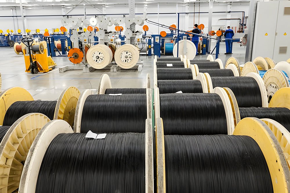
2. Why China Is the Best Place to Buy Fibre Optic Cable: The Key Advantages
The overwhelming majority of global buyers choose China when deciding where to buy fibre optic cable. Here’s a detailed breakdown of the compelling benefits.
Unbeatable Cost Advantage
China’s massive scale and efficient manufacturing deliver the lowest prices in the world without sacrificing quality for standard products.
Typical 2026 pricing comparison (144-fiber loose-tube outdoor cable, per meter, FOB):
- China (Tier-1/1.5 manufacturers): $1.20–$1.80
- USA (Corning/Prysmian): $3.50–$4.80
- Europe: $3.80–$5.20
- India: $1.80–$2.50
Even after adding ocean freight (15–25%) and import duties, Chinese cable remains 40–60% cheaper. For a 500 km project, this translates to $800,000–$1.5 million in savings—enough to fund additional network segments or upgrades.
Direct factory purchasing eliminates middlemen markups (30–50%), making China the smartest choice for buyers looking to buy fibre optic cable at competitive rates. Volume discounts for large orders can reach 40%, further widening the gap.
Equivalent or Superior Quality
China is home to the world’s top fiber producers:
- YOFC (world’s largest preform/fiber maker)
- Hengtong, FiberHome, ZTT, Futong — all ranking in global top 10
These manufacturers use the same Corning-licensed technology as Western brands, producing G.652D/G.657A2 fibers meeting or exceeding ITU-T standards. Independent testing shows Chinese Tier-1 cable matches or surpasses U.S./European equivalents in attenuation, tensile strength, and environmental performance.
China’s massive production volume enables rigorous quality control—100% OTDR testing, full mechanical/environmental validation—often at lower cost than smaller Western factories.
For buyers who need certified, high-quality cable to buy fibre optic cable, China delivers premium performance without premium pricing.
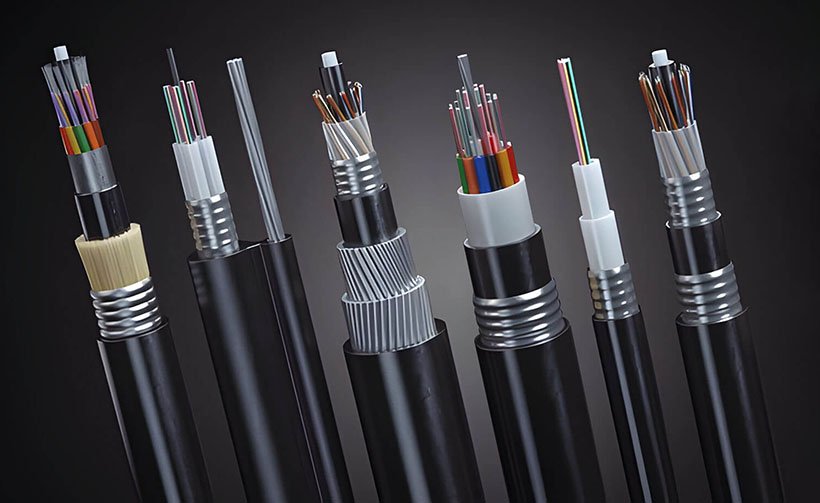
Unmatched Product Variety and Customization
China offers the broadest range available anywhere:
- Single-mode/multimode
- Loose-tube, ribbon, micro-cable, tight-buffered
- Aerial (figure-8, ADSS), buried (armored), duct, submarine
- Hybrid fiber-power for 5G remote powering
- Fiber counts from 1 to 1728
Need a custom 288-fiber figure-8 with specific messenger diameter, recycled sheath, or special armor? Chinese factories routinely handle such requests with minimum orders as low as 10 km.
Western manufacturers often require larger MOQs or charge premiums for customization. China’s flexibility makes it ideal for diverse projects when you buy fibre optic cable.
Fast Lead Times and Reliable Supply Chain
- Standard orders: 7–21 days from PO to container loading.
- Urgent needs: 3–5 days possible with priority production.
- Massive capacity: No backlogs even for million-kilometer orders.
Compare to U.S./Europe: 8–20 weeks due to lower production volume and fiber imports (often from… China).
China’s logistics infrastructure—major ports in Shanghai, Ningbo, Qingdao—ensures reliable global shipping with multiple weekly sailings.
Complete Vertical Integration and Supply Stability
China controls ~96% of global preform production and ~85% of cable manufacturing. This integration ensures stable supply, consistent quality, and rapid adoption of innovations like G.657A2 bend-insensitive fiber or low-smoke zero-halogen sheaths.
Buyers sourcing from China avoid supply chain vulnerabilities seen in other regions, especially post-pandemic disruptions.
Strong Export Support and International Experience
Chinese manufacturers have decades of experience exporting to 150+ countries, with:
- English/Spanish/Arabic support teams
- Overseas warehouses in Europe, Middle East, Africa
- Familiarity with international standards (UL, CE, RoHS)
When you buy fibre optic cable from China, you get global-class service.

3. Top Chinese Manufacturers to Buy Fibre Optic Cable From
When choosing where to buy fibre optic cable in China, focus on established Tier-1 and Tier-1.5 manufacturers with proven export records:
- YOFC (Yangtze Optical Fibre and Cable) — World’s largest; premium quality matching Corning.
- Hengtong Optic-Electric — Submarine and OPGW specialist; strong in power utility projects.
- FiberHome — Full solutions including ODN and splitters.
- ZTT (Jiangsu Zhongtian Technology) — ADSS and aerial cable expert.
- Futong Group — Excellent price-performance ratio.
- KomunikasiMesh — Best balance of quality, cost, and service; fast customization and international support.
4. How to Safely and Effectively Buy Fibre Optic Cable from China
Direct Factory Purchasing Process
- Contact manufacturers via official websites or verified Alibaba accounts.
- Request product catalogs, test reports, and factory certifications.
- Ask for free samples (most Tier-1 factories provide them).
- Negotiate MOQ, pricing, and payment terms.
Verification Steps to Avoid Risks
- Check supplier certificates from China Mobile/Unicom/Telecom frameworks.
- Request third-party inspection (SGS, TÜV, Intertek) at factory.
- Verify production capacity and export history.
- Use trade assurance platforms for initial orders.
Payment and Logistics Best Practices
- Standard: 30% T/T deposit, 70% against B/L copy.
- L/C at sight for orders >$500k.
- Sea freight 20–35 days; air freight 5–9 days for urgent.
- Choose experienced forwarders familiar with dangerous goods (some cables contain gel).
Risk Mitigation Strategies
- Start with small trial orders.
- Include detailed technical specifications in contract.
- Specify warranty terms (typically 1–5 years).
- Use escrow services for peace of mind.
Following these steps ensures safe, successful purchases when you buy fibre optic cable from China.
5. Comparison with Buying from Other Regions
While China dominates, other regions have niche advantages:
- United States: Strong local support, “Made in USA” for government contracts, but 2–3× higher prices and longer lead times.
- Eropa: EU compliance, premium branding, but highest costs and smaller scale.
- India: Competitive pricing (20–30% above China), growing quality, but inconsistent supply and longer lead times.
For 90% of global buyers in 2026 — especially those prioritizing cost, variety, and speed — China offers the best combination when deciding where to buy fibre optic cable.
Conclusion: The Clear Answer Is China
When asking “where can I buy fibre optic cable?”, the answer for most buyers in 2026 is clear: China.
The combination of lowest prices, equivalent or superior quality, vast variety, fast delivery, stable supply chain, and strong export support makes China the optimal source to buy fibre optic cable.
CommMesh is ready to be your trusted partner — with premium quality, competitive pricing, fast customization, and dedicated international service.
Contact CommMesh today to get quotes, samples, or start your order. Your next successful project begins with the right source to buy fibre optic cable.
]]>Also known as fiber adapter, optical fiber adapter, fiber coupler, fiber optic coupler, mating sleeve, or simply adapter, this component is ubiquitous in every fiber network — from FTTH drop terminations to hyperscale data center interconnects and 800G/1.6T Ethernet deployments.
This exhaustive guide covers every aspect of fiber optic adapters in 2026: their fundamental definition and purpose, historical evolution, detailed construction and materials, comprehensive classification of all major types, key performance specifications and industry standards, real-world applications across industries, installation best practices and handling tips, compatibility and hybrid adapter solutions, cost analysis and pricing trends, common pitfalls and troubleshooting techniques, quality control and testing requirements, real-world case studies, and emerging innovations through 2030.
1. What Is a Fiber Optic Adapter? Definition, Purpose, and Fundamental Role
A adaptor serat optik is a passive mechanical device that precisely aligns and joins two fiber optic connectors (male-to-male), allowing optical signals to pass from one fiber to another with minimal insertion loss and back-reflection.
Unlike active components (transceivers, amplifiers, repeaters), adapters contain no electronics — they are purely mechanical alignment tools.
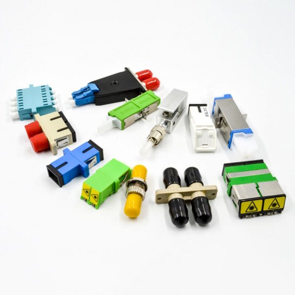
1.1 Core Functions in Detail
- Ferrule Alignment: Centers the two ceramic ferrules (2.5 mm for SC/FC/ST, 1.25 mm for LC/MU) so fiber cores align within 0.5–1 micron.
- Physical Contact: Ensures direct contact (PC/UPC) or angled contact (APC) between fiber endfaces to eliminate air gaps and minimize Fresnel reflection.
- Mechanical Stability: Provides secure mating under vibration, temperature changes, and pull forces (≥100 N typical), preventing intermittent connections.
- Connector Type Conversion: Enables hybrid adapters (e.g., SC to LC) for legacy-to-modern transitions without replacing entire cable runs.
- Density Enablement: Allows high-density mounting in fiber patch panels, cassettes, wall boxes, and ODFs, supporting 576+ ports per 1U rack.
- Safety and Protection: Shuttered adapters automatically close when unmated, reducing eye exposure to laser light and protecting against dust.
Without reliable adapters, even the best fiber cable and transceivers would suffer from high insertion loss, excessive reflections, and intermittent failures.
1.2 Why Adapters Are Critical in 2026
- Density Explosion: Data centers now pack 576+ LC ports per 1U rack, with quad LC adapters pushing 1152 ports.
- High-Speed Requirements: 800G/1.6T coherent optics demand ≤0.10 dB insertion loss and ≥65 dB return loss.
- PON & FTTH: APC adapters are mandatory to prevent reflection-induced errors in OLT receivers, especially at 50G/100G rates.
- Legacy Migration: Hybrid adapters bridge old SC/FC systems with modern LC/MPO penempatan.
- Safety & Reliability: Shuttered adapters reduce eye exposure to laser light and protect against dust contamination.
A single poor-quality adapter can cause 0.5–1 dB loss, turning a 100 km link into an unreliable one and costing operators millions in troubleshooting and downtime.
1.3 Historical Evolution of Fiber Optic Adapters
- 1980s: Early metal sleeves for FC/ST connectors; manual alignment with limited precision.
- 1990s: Plastic adapters for SC and LC emergence; ceramic sleeves introduced for better alignment.
- 2000s: High-precision zirconia for 10G+ speeds; APC polish for PON and analog video.
- 2010s: Hybrid adapters for 40G/100G; shuttered designs for safety and dust protection.
- 2020s: MPO/MTP adapters for parallel optics; VSFF (Very Small Form Factor) like SN/MDC for 1.6T+.
- 2026+: Smart adapters with RFID and integrated monitoring.
2. Detailed Construction and Materials of Fiber Optic Adapters
2.1 Core Components and Their Functions
- Alignment Sleeve: Zirconia ceramic (premium, ±0.001 mm tolerance) or phosphor bronze (budget, ±0.005 mm). The sleeve is the heart of the adapter, centering the ferrules.
- Housing/Body: Zinc alloy, stainless steel, or high-grade plastic (UL94 V-0 rated) with mounting flanges for panel installation.
- Split Sleeve: Spring-loaded mechanism that holds connectors securely under constant pressure.
- Dust Cap/Shutter: Metal or plastic cap; shuttered versions automatically close when unmated for laser safety and dust protection.
- Keying/Notch: Ensures correct orientation (especially for APC to prevent UPC mating).
2.2 Ferrule Alignment Tolerance
- Ceramic Sleeve: Tolerance ±0.001 mm → lowest insertion loss and best repeatability.
- Bronze Sleeve: Tolerance ±0.005 mm → acceptable for multimode, higher IL in single-mode.
Premium adapters use zirconia sleeves for both SM and MM.
2.3 Housing Variations
- Simpleks: Single connector mating.
- Rangkap: Two connectors (most common for SC/LC).
- Quad: Four konektor LC for ultra-density.
- Panel-Mount: Flanged for rack mounting.
- Bulkhead: For wall or box penetration.
- Hybrid: SC to LC, LC to FC, LC to MPO, etc.
2.4 Polish Compatibility
- UPC (Ultra Physical Contact): Flat polish, blue housing, ≥50–55 dB return loss.
- APC (Angled Physical Contact): 8° angle, green housing, ≥60–70 dB return loss.
- komputer (Physical Contact): For multimode, ≥30 dB return loss.
Mixing UPC/APC causes severe reflection (–35 to –45 dB).
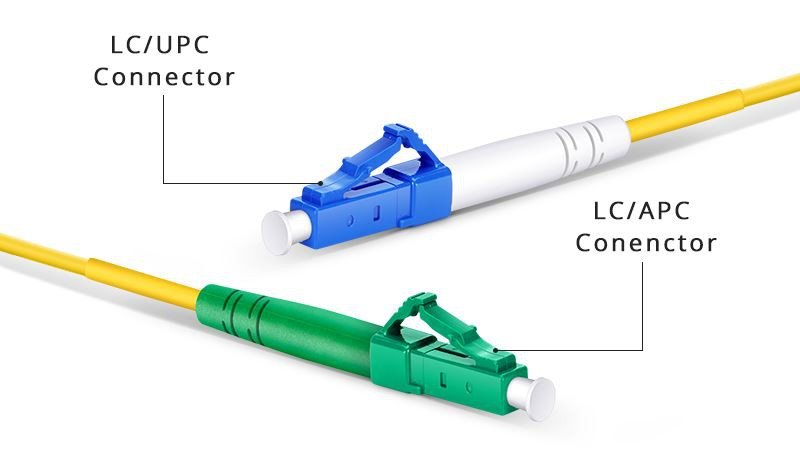
2.5 Materials and Manufacturing Quality
- Premium: Zirconia ceramic sleeve, stainless steel housing.
- Standard: Ceramic sleeve, zinc alloy housing.
- Budget: Bronze sleeve, plastic housing.
CommMesh uses zirconia sleeves in all adapters for consistent ≤0.08 dB insertion loss.
3. Comprehensive Classification of Fiber Optic Adapter Types
3.1 By Connector Type (Most Common)
| Jenis Adaptor | Ukuran Ferrule | Housing Color | Typical Applications | 2025 Market Share |
|---|---|---|---|---|
| Adaptor SC | 2,5 mm | Blue (UPC) / Green (APC) | FTTH, telecom, CATV | 45% |
| Adaptor LC | 1,25 mm2 | Blue / Green | Data centers, high-density panels | 40% |
| Adaptor FC | 2,5 mm | Silver | Test equipment, precision applications | 6% |
| Adaptor ST | 2,5 mm | Black | Legacy enterprise, industrial | 3% |
| Adaptor MU | 1,25 mm2 | Biru | High-density telecom | 2% |
| MPO/MTP Adapter | Multi-fiber | Black | 40G–1.6T parallel optics | 4% (growing) |
| E2000 Adapter | 2,5 mm | Hijau | Europe, secure environments | 1% |
SC and LC dominate >85% of the market in 2026.
3.2 By Fiber Mode
- Single-Mode Adapters: Tighter tolerances (0.125 mm sleeve) for OS2 fibers.
- Multimode Adapters: Larger alignment for OM3/OM4/OM5.
3.3 By Polish Type
- UPC (Ultra Physical Contact): Flat, ≥50–55 dB return loss.
- APC (Angled Physical Contact): 8° angle, ≥60–70 dB return loss.
- komputer (Physical Contact): For multimode, ≥30 dB return loss.
3.4 By Configuration
- Simplex: Single connection.
- Duplex: Two connectors (most common for SC/LC).
- Quad: Four LC connectors.
- Hybrid: SC to LC, LC to FC, LC to MPO, etc.
3.5 By Mounting Style
- Panel-Mount: Flanged for rack panels.
- Bulkhead: For wall or box penetration.
- Coupler: Free-standing mating sleeve.
3.6 Special-Purpose Adapters
- Shuttered Adapters: Automatic shutter for laser safety.
- Hybrid Adapters: For legacy-to-new transitions.
- Attenuated Adapters: Built-in fixed attenuation (1–20 dB).
- Switchable Adapters: Manual polarity swap.
4. Performance Specifications and Industry Standards
4.1 Optical Performance
- Insertion Loss: ≤0.10 dB (premium), ≤0.20 dB (standard)
- Return Loss: UPC ≥55 dB, APC ≥65 dB
- Repeatability: ≤0.1 dB (1000 matings)
4.2 Mechanical Performance
- Mating Cycles: 500–1000
- Operating Temperature: –40°C to +85°C
- Vibration: 10–2000 Hz, 10 G
4.3 Environmental Performance
- Humidity: 95% RH non-condensing
- Dust Protection: IP54 (panel-mount)
4.4 Compliance Standards
- IEC 61754 (connector interfaces)
- Telcordia GR-326 (reliability)
- RoHS/REACH (environmental)
- UL 94 V-0 (flammability)
- TIA/EIA-604 (FOCIS)
CommMesh adapters achieve ≤0.08 dB IL and ≥68 dB RL (APC).
5. Applications Across Industries
5.1 Data Centers and Enterprise
- LC adapters for high-density 400G/800G panels.
- MPO adapters for parallel optics breakouts.
5.2 FTTH and PON Networks
- SC/APC adapters in termination boxes and closures.
5.3 Telecom and Backbone
- FC adapters for test equipment.
- SC adapters for central offices.
5.4 Industrial and Harsh Environments
- E2000 or ruggedized SC for factories.
5.5 Broadcast and CATV
- SC/APC for analog video.
5.6 Test & Measurement
- FC adapters for precision instruments.
6. Installation Best Practices and Handling Tips (Expanded)
6.1 Preparation Before Installation
- Inspection: Use 200×–400× inspection scope to check endface for scratches, contamination, or chips.
- Pembersihan: Use one-click cleaner (type A for 1.25 mm, type B for 2.5 mm) on both connectors and adapter sleeve.
- Lingkungan: Work in clean area; avoid dust.
6.2 Mating Process
- Remove dust cap carefully.
- Align keying (APC notch must match).
- Push firmly until click (SC) or latch engages (LC).
- Avoid twisting or forcing.
6.3 Torque for Threaded Types
- FC/ST: 0.9 N·m (use torque wrench).
- Over-tightening damages ferrule.
6.4 Safety Considerations
- Never look into live fiber.
- Use shuttered adapters for live systems.
- Label polarity and type.
6.5 Common Mistakes and Fixes
- Mixing UPC/APC → severe reflection → replace immediately.
- Contamination → clean both ends and sleeve.
- Loose mating → re-seat or replace.
7. Cost Analysis and Pricing Trends 2026 (Expanded)
7.1 Upfront Pricing
| Type (duplex) | Price Range USD | Bulk (10k+) Discount |
|---|---|---|
| SC UPC Simplex | 0.80–1.50 | 40–60% |
| LC APC Duplex | 1.20–2.00 | 45–65% |
| MPO 12-fiber | 5.00–8.00 | 50–70% |
| Hybrid SC-LC | 1.80–3.00 | 40–55% |
7.2 Total Cost of Ownership Factors
- Initial price
- Failure rate (poor quality = 5–10% failure vs premium <1%)
- Maintenance (cleaning, replacement)
- Downtime cost
7.3 Procurement Strategies
- Direct from manufacturers for 30–50% savings.
- Request sample testing.
- Prefer suppliers with full traceability and OTDR reports.
8. Common Pitfalls and Troubleshooting Techniques (Expanded)
8.1 Most Frequent Issues
- Kontaminasi: Dust or oil on endface → 0.5 dB loss. Fix: Clean with one-click and inspect.
- Polish Mismatch: UPC to APC → –35 dB RL. Fix: Replace with correct type.
- Loose Mating: Intermittent signal. Fix: Re-seat or replace spring.
- Over-tightening: Cracked ferrule. Fix: Use torque wrench.
8.2 Advanced Troubleshooting
- Use OTDR to locate high-loss point.
- Video inspection scope for endface analysis.
- Power meter for end-to-end loss.
9. Innovations and Trends 2026–2030 (Expanded)
9.1 Very Small Form Factor (VSFF) Adapters
- SN, MDC, CS connectors for 1.6T+ density.
9.2 Shuttered and Smart Adapters
- Automatic shutter for laser safety.
- RFID for inventory tracking.
9.3 Sustainable Materials
- Recycled plastics and biodegradable components.
9.4 Hybrid and Multi-Fiber
- More LC to MPO hybrids for breakout.
Conclusion: Mastering Fiber Optic Adapters for Future Networks
Fiber optic adapters are small but vital. Choose quality for performance.
CommMesh offers premium adapters — contact us.
]]>As of January 2026, with global fiber deployments exceeding 1.6 billion fiber-kilometers annually, FTTH connections surpassing 2.5 billion households, and data centers adopting 800G/1.6T interconnects requiring ultra-high-density management, understanding the precise differences between a fiber patch panel dan sebuah ODF is essential for efficient architecture, cost optimization, scalability, and long-term reliability.
This extended definitive guide examines every facet of the Fiber Patch Panel vs ODF comparison. We define each component in depth, explore construction and design variations, compare technical specifications and performance metrics, analyze applications across industries with real-world examples, provide detailed installation methodologies and best practices, evaluate cost implications including total cost of ownership (TCO), present case studies from global deployments, debunk common myths and misconceptions, address compatibility, migration strategies, and hybrid scenarios, and forecast innovations shaping these products through 2030.
1. Defining the Two Components: Core Purposes, Functions, and Historical Context
1.1 What Is a Fiber Optic Patch Panel?
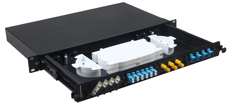
A fiber optic patch panel (also known as fiber distribution panel, fiber patch bay, optical patch panel, atau fiber termination panel) is a modular, rack-mountable unit designed for high-density fiber termination, organization, and cross-connection in structured cabling environments.
Primary functions:
- Terminate incoming backbone, feeder, or horizontal cables.
- Provide modular adapter interfaces (SC, LC, MPO, etc.) for patching to equipment pigtails or jumpers.
- Enable flexible reconfiguration through patch cords without new splicing.
- Organize splices using internal trays and manage slack with routing rings.
- Serve as interconnection hubs in horizontal or backbone cabling hierarchies.
Typical locations:
- Data centers (main distribution area/MDA, intermediate distribution area/IDA, horizontal distribution area/HDA).
- Enterprise main distribution frames (MDF) and intermediate distribution frames (IDF).
- Telecom equipment rooms.
- Campus backbone distribution points.
- Broadcast and CATV facilities.
Patch panels act as the flexible “workhorse” for day-to-day fiber management, allowing technicians to perform moves, adds, and changes (MACs) quickly and efficiently.
Historical context: Patch panels evolved from copper telephone cross-connect blocks in the 1990s, adapting to fiber with the rise of structured cabling standards like TIA/EIA-568. The introduction of LC connectors in the early 2000s dramatically increased density, making patch panels essential for data center growth.
1.2 What Is an ODF (Optical Distribution Frame)?
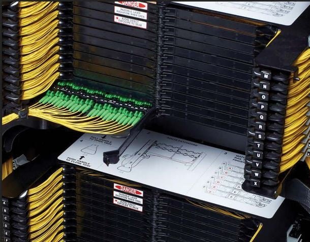
Sebuah ODF (Optical Distribution Frame) is a large-scale, centralized fiber management system that integrates termination, splicing, patching, and distribution in a dedicated frame or cabinet.
Primary functions:
- High-capacity termination of incoming feeder cables from external plant.
- Mass splicing between feeder and internal distribution cables.
- Cross-connection between different network segments or customers.
- Integration of passive components like splitters for PON architectures.
- Comprehensive cable routing, slack management, and protection for thousands of fibers.
Typical locations:
- Telecom central offices and headends.
- National or regional backbone nodes.
- Large data center main distribution areas (MDA).
- Carrier-neutral facilities and colocation hubs.
ODFs serve as the “command center” for massive fiber counts, providing structured hierarchy and long-term organization.
Historical context: ODFs originated in the 1980s for telecom main distribution frames, evolving from copper MDFs. The 1990s–2000s saw ODFs become standard for Jaringan FTTH feeder distribution, with modern ODFs incorporating modular trays and high-density adapters.
1.3 Fundamental Comparison Table
| Aspek | Fiber Optic Patch Panel | Optical Distribution Frame (ODF) |
|---|---|---|
| Primary Role | Modular cross-connect and local distribution | Centralized high-capacity termination and routing |
| Scale | Small to medium (1U–6U, 24–576 ports) | Large (full rack/cabinet, 576–5000+ fibers) |
| Location | Rack in equipment room/data center | Dedicated ODF room or large telecom facility |
| Port Density | High per rack unit | High overall but lower per unit height |
| Reconfiguration Flexibility | High (easy front patching) | Structured (may require rear access) |
| Kapasitas Sambungan | Limited (1–4 trays) | High (dozens of trays) |
| Cable Entry | Rear glands | Multiple large entry points |
| Typical Users | Enterprises, data centers, small telecom | Major operators, national backbones |
| Future Scalability | High (modular stacking) | Very high (designed for expansion) |
2. Detailed Construction and Design Differences
2.1 Fiber Optic Patch Panel Construction
Patch panels are built for modularity and rack integration.
- Chassis Material: Cold-rolled steel or aluminum with powder coating for durability and EMI shielding.
- Front Panel: Modular adapter plates supporting Bahasa Inggris, Bahasa Inggris, MPO, Bahasa Inggris, E2000, etc., with color-coded dust shutters and clear labeling strips.
- Rear Access: Multiple cable entry points with rubber glands, strain relief boots, grounding bars, and cable tie points.
- Internal Features: Sliding or fixed splice trays (24–48 splices per tray), cable routing rings, slack storage spools, vertical/horizontal cable managers.
- Variants:
- Loaded (pre-installed adapters/pigtails)
- Unloaded (empty for custom configuration)
- High-density sliding drawer for rear access
- Angled panels for improved cable routing
- Pre-terminated with MPO trunks for data center
Modern 2026 panels include tool-less adapter plate installation, integrated cable management arms, and optional smart monitoring ports.
2.2 ODF Construction
ODFs are large-scale systems for centralized management.
- Frame Structure: Full-height 19-inch or 21-inch rack or dedicated cabinet with reinforced base for stability.
- Modules: Swing-out or sliding frames containing splice trays, splitter holders, and adapter panels.
- Perutean Kabel: Extensive vertical and horizontal cable managers, overhead troughs, and under-floor routing options.
- Doors and Security: Lockable front/rear doors with ventilation and cable access grommets.
- Integration Features: Built-in splitter modules, monitoring ports, grounding busbars, and labeling systems.
ODFs often include seismic bracing for earthquake-prone regions.
2.3 Size, Form Factor, and Capacity Comparison
Patch panels: Standardized 19-inch width, 1U (44 mm) to 6U height, supporting 96–576 ports.
ODFs: Full cabinets (42U–48U height), accommodating 1000–5000+ fibers with multiple modules.
Patch panels excel in density per rack unit; ODFs in overall capacity and structured organization.
3. Functionality and Technical Specifications
3.1 Capacity and Scalability
Patch panels scale by stacking multiple units in racks.
ODFs provide integrated scalability within a single frame.
3.2 Optical Performance
Both support premium adapters with ≤0.15 dB insertion loss and ≥65 dB return loss (APC).
3.3 Environmental Protection
Patch panels: Indoor IP20/IP40.
ODFs: Indoor with optional seismic and fire ratings.
3.4 Cable Management and Re-entry
Patch panels: Front-focused for quick patching.
ODFs: Rear/front access with swing-out modules for large-scale re-entry.
3.5 Splicing and Termination Options
Patch panels: Limited trays for local splicing.
ODFs: High-capacity trays for feeder splicing.
4. Applications and Use Cases Across Industries
4.1 Fiber Optic Patch Panel Applications
- Pusat Data: High-density cross-connect between core switches, servers, and storage.
- Jaringan Perusahaan: MDF/IDF for structured cabling to work areas.
- Small Telecom Nodes: Local distribution in regional offices.
- Broadcast Facilities: Video headend patching.
- Campus Networks: Building-to-building links.
4.2 ODF Applications
- Telecom Central Offices: Feeder cable termination and PON OLT distribution.
- National Backbone Nodes: High-count splicing for long-haul.
- Large Data Center MDA: Main distribution for thousands of fibers.
- Carrier Hotels: Interconnection between operators.
4.3 Hybrid and Overlapping Scenarios
Many facilities use ODF for feeder termination and patch panels for distribution.
5. Installation and Deployment Methodologies
5.1 Installing a Fiber Optic Patch Panel
- Rack mounting with proper alignment.
- Rear cable entry and strain relief.
- Adapter plate installation.
- Pigtail splicing or pre-terminated loading.
- Front labeling and testing.
5.2 Installing an ODF
- Frame assembly and anchoring.
- Feeder cable routing through entry points.
- Mass splicing in trays.
- Cross-connect patching.
- Documentation and testing.
6. Cost Analysis and Total Cost of Ownership 2026
6.1 Upfront Pricing
| Item | Patch Panel Price | ODF Price |
|---|---|---|
| 96-port high-density | $300–$600 | Tidak tersedia |
| Full ODF (2000 fibers) | Tidak tersedia | $5,000–$12,000 |
6.2 Total Cost of Ownership
Patch panels lower per-port cost at scale.
ODFs higher initial but structured for long-term.
7. Advantages and Limitations
7.1 Patch Panel
Advantages: Flexible, modular, easy MACs. Limitations: Limited capacity per unit.
7.2 ODF
Advantages: High capacity, structured organization. Limitations: Higher cost, space requirements.
8. Innovations and Trends 2026–2030
- Modular ODF with hot-swappable trays
- High-density patch panels with AI routing
- Smart monitoring integration
CommMesh leads with hybrid solutions.
Conclusion: Choosing the Right Solution
Fiber optic patch panels for modular distribution; ODF for large-scale centralized management.
CommMesh offers both — contact us for your needs.
]]>Bahasa Inggris (Subscriber Connector) and Bahasa Inggris (Lucent Connector, also called Little Connector) are the two dominant connector types powering modern networks—from Jaringan FTTH drops and PON infrastructure to hyperscale data centers running 800G and 1.6T Ethernet. As of January 2026, with global fiber connections exceeding 2.5 billion and high-density architectures pushing physical limits, understanding SC vs LC fiber connectors is essential for network architects, engineers, procurement teams, installers, and operators.
This exhaustive guide provides the most comprehensive comparison of SC vs LC fiber connectors available. We cover their history and evolution, physical and mechanical design differences, optical performance metrics, density and space efficiency, real-world applications across industries, installation and handling considerations, polarity management, cost analysis, compatibility and migration strategies, common myths debunked, emerging trends for 2026–2030, and a practical decision framework.
Authored by CommMesh — a Tier-1 manufacturer producing both SC and LC assemblies for telecom operators — this article delivers unbiased, data-driven insights to help you select the optimal connector for your current and future networks.
1. Historical Background and Evolution of SC and LC Connectors
1.1 The Birth of SC: The Subscriber Connector Revolution
Developed by Japanese telecom giant NTT in the mid-1980s, the konektor SC was designed as a robust, easy-to-use alternative to the threaded FC connector. Its push-pull mechanism, 2.5 mm ceramic ferrule, and square housing made it ideal for high-volume telecom deployments.
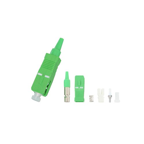
Key milestones for SC:
- Late 1980s: First commercial use in Japanese telecom networks.
- 1990s: Becomes global standard for central offices and early FTTH trials.
- 2000s: SC/APC (angled polish) dominates PON and CATV due to superior return loss.
- 2010s–2020s: Remains the preferred connector for outside plant (OSP) in FTTH, especially drop cables and ONT terminations.
- 2026 status: Still the most common connector in global FTTH installations (estimated 55% market share in OSP).
The SC’s larger size and rugged design made it perfect for field technicians working in manholes, aerial splices, and customer premises.
1.2 The Rise of LC: The Density Champion
Invented by Lucent Technologies (now Nokia) in the late 1990s, the konektor LC addressed the growing need for higher port density. By halving the ferrule diameter to 1.25 mm and using an RJ45-style latch, LC enabled twice the connections in the same space.
Key milestones for LC:
- Late 1990s: Introduced with SFP transceivers.
- Early 2000s: Rapid adoption in enterprise and data center switching.
- 2010s: Becomes standard for 40G/100G QSFP breakouts and high-density panels.
- 2020s: Dominant in 400G/800G QSFP-DD and OSFP modules; uniboot and quad designs emerge.
- 2026 status: Controls ~70% of data center and high-speed interconnect market.
LC’s small form factor revolutionized panel density and transceiver design.

1.3 The Ongoing SC vs LC Debate in 2026
While LC has largely won the density battle, SC maintains strong positions in legacy telecom, FTTH OSP, and applications requiring ruggedness. Hybrid networks using both are common, creating demand for SC-LC hybrid patch cords.
The choice affects:
- Port density and rack space
- Installation speed and technician skill
- Maintenance and troubleshooting
- Upgrade path to higher speeds
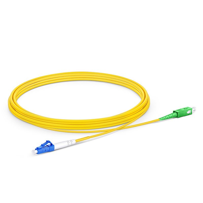
2. Physical Design and Mechanical Comparison
2.1 Size and Footprint
- Bahasa Inggris: 2.5 mm ferrule, ~13 mm wide housing
- Bahasa Inggris: 1.25 mm ferrule, ~6.25 mm wide (half SC footprint)
LC enables 2× density in panels and 4× with quad adapters.
2.2 Coupling Mechanism
- Bahasa Inggris: Push-pull (insert and pull collar)
- Bahasa Inggris: Latch (press tab like RJ45)
SC is more forgiving in dirty/gloved environments; LC latch can break if mishandled.
2.3 Duplexing
- Bahasa Inggris: Separate duplex clip
- Bahasa Inggris: Integrated duplex housing or uniboot designs
LC uniboot allows polarity flip without tools.
2.4 Ferrule and Polish
Both use zirconia ferrules with:
- UPC (flat, blue housing): ≥50–55 dB return loss
- APC (8° angle, green housing): ≥60–65 dB return loss
No inherent performance difference in polish quality.
2.5 Durability and Mating Cycles
- Both rated 500–1000 matings
- SC’s larger size resists damage better in field
- LC more susceptible to latch failure
3. Optical Performance: Head-to-Head Metrics
| Parameter | SC Connector (Premium) | LC Connector (Premium) | Catatan |
|---|---|---|---|
| Insertion Loss (typical) | 0.10–0.20 dB | 0.10–0.20 dB | Identical |
| Insertion Loss (max) | ≤0.30 dB | ≤0.30 dB | |
| Return Loss UPC | ≥55 dB | ≥55 dB | |
| Return Loss APC | ≥65 dB | ≥65 dB | APC mandatory for PON |
| Repeatability | ≤0.1 dB (1000 matings) | ≤0.1 dB (1000 matings) | |
| Temperature Stability | Excellent | Excellent |
Performance is essentially the same when manufactured to high standards.
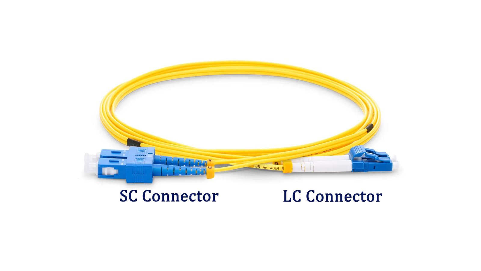
4. Density and Space Efficiency: LC’s Biggest Advantage
4.1 Patch Panel Density
- Bahasa Inggris: 24–48 ports per 1U panel
- Bahasa Inggris: 96–144 ports per 1U (standard duplex)
- Quad LC: Up to 576 ports per 1U
In 800G data centers, LC density saves millions in real estate.
4.2 Transceiver Impact
- SFP/SFP+: LC duplex
- QSFP28/QSFP-DD/OSFP: LC breakouts or MPO
LC enables smaller, higher-density modules.
4.3 Cable Management
LC’s smaller footprint simplifies routing in crowded trays.
5. Applications: Where SC and LC Excel in 2026
5.1 SC Connector Applications
- FTTH Outside Plant: SC/APC pigtails in fiber optic closures, drop cables to ONT.
- CATV/RFoG: SC/APC for analog video overlay.
- Telecom CO/Headend: Legacy SC panels.
- Industrial/Harsh Environments: Rugged SC for factories, oil rigs.
5.2 LC Connector Applications
- Pusat Data: High-density panels, transceivers (SFP, QSFP).
- Enterprise LAN: LC for switch uplinks.
- Hyperscale DCI: 400G/800G breakout to LC.
- Campus Networks: Compact LC patching.
5.3 Hybrid Use Cases
Many operators use SC/APC in OSP and LC in data centers, requiring SC-LC hybrid cords.
6. Cost Analysis 2026
| Item (duplex, 3m, single-mode) | SC Price | LC Price | Catatan |
|---|---|---|---|
| OS2 UPC | $3.20–$5.00 | $2.50–$4.20 | LC cheaper at scale |
| OS2 APC | $3.80–$5.80 | $3.00–$4.80 | APC premium ~10% |
| Multimode OM4 | $4.50–$6.50 | $3.50–$5.50 | |
| Bulk pigtail (12-pack) | $22–$32 | $18–$28 |
LC’s manufacturing scale and smaller size drive 10–20% lower costs.
7. Installation and Handling Considerations
7.1 Ease of Use
- SC: Larger, easier to grip with gloves; push-pull forgiving.
- LC: Smaller latch requires dexterity; prone to breakage if mishandled.
7.2 Cleaning and Inspection
Both require meticulous cleaning, but LC’s smaller ferrule makes contamination harder to spot without high-magnification scopes.
Best practice: IEC 61300-3-35 compliant inspection.
7.3 Polarity Management
- SC: Fixed polarity; requires keyed adapters for Type B.
- LC: Uniboot or flipable designs allow field polarity change.
LC offers greater flexibility.
8. Compatibility, Migration, and Hybrid Strategies
- SC to LC hybrid patch cords common for transitions.
- Adapters available but add ~0.5 dB loss and failure points.
Best strategy: Standardize on LC for new builds, maintain SC for legacy OSP.
9. Myths and Misconceptions Debunked
Myth 1: “SC is more reliable than LC”
Reality: Reliability depends on manufacturing quality, not size.
Myth 2: “LC has higher insertion loss”
Reality: Identical when properly made.
Myth 3: “You can’t use LC in outdoor environments”
Reality: Ruggedized LC (hardened adapters) common in FTTH.
Myth 4: “SC is obsolete”
Reality: Still dominant in global FTTH OSP (estimated 1.4 billion SC/APC connections).
Myth 5: “APC is only for video”
Reality: APC mandatory for all PON to prevent reflection interference.
10. Future Trends in SC and LC Connectors 2026–2030
10.1 LC Evolution
- Uniboot, push-pull LC for easier handling
- Quad LC and very small form factor (VSFF) like SN/MDC challenging LC in ultra-density
- LC in co-packaged optics roadmaps
10.2 SC Persistence
- Continued dominance in FTTH OSP
- Hardened SC for 5G fronthaul
10.3 Overall Shift
Density demands will push LC (and successors) to >80% market share by 2030.
Conclusion: Making the Right Choice in 2026
For new high-density, high-speed deployments (data centers, enterprise, 400G+), Bahasa Inggris is the clear winner.
For FTTH outside plant, legacy telecom, or rugged field environments, Bahasa Inggris — particularly SC/APC — remains essential.
The optimal modern strategy: Use LC for indoor/high-density, SC/APC for PON OSP, with hybrid cords for transitions.
CommMesh manufactures both with premium performance (≤0.12 dB IL, ≥68 dB RL APC).
Contact us for hybrid assemblies, migration planning, or bulk pricing.
Your network’s reliability starts with the right connector — choose wisely.
]]>