Fiber optic cables are the lifeline of modern telecommunications, delivering high-speed data with minimal loss. However, installing and maintaining these networks requires seamless connections between fiber segments—a process known as fiber optic splicing. This technical guide explores the principle of fiber optic splicing, delving into its methods, equipment like the fiber optic splicer and fiber optic splicer machine, and best practices. Designed for telecom professionals and distributors sourcing solutions from CommMesh, this article provides actionable insights to ensure reliable network performance.
What is Fiber Optic Splicing?
Fiber optic splicing is the process of joining two fiber optic cables to create a continuous optical path. This is essential for extending network reach, repairing breaks, or connecting cables in data centers and telecom infrastructure. The goal is to align the microscopic glass cores (typically 8–62.5 μm in diameter) with precision, minimizing signal loss and reflection. Splicing differs from connectors, which are detachable, as it forms a permanent or semi-permanent bond.
The principle hinges on maintaining the integrity of light transmission. When light travels through a fiber, it relies on total internal reflection within the core, guided by the refractive index difference between the core (e.g., 1.46) and cladding (e.g., 1.44). Any misalignment or imperfection at the splice point can cause attenuation (0.1–0.5 dB) or back reflection (-50 to -70 dB), degrading performance. Splicing techniques—fusion and mechanical—address these challenges, with tools like the fiber optic splicer machine playing a pivotal role.
Principles of Fiber Optic Splicing
The core principle of fiber optic splicing is to achieve low-loss, high-strength junctions between fiber ends. This involves three key steps: preparation, alignment, and bonding. Let’s break it down technically:
- Preparation
- Fibers are stripped of their protective layers (jacket, buffer, coating) to expose the bare glass, typically 125 μm in diameter with an 8–10 μm core for single-mode.
- Cleaving is critical—using a precision cleaver, the fiber is cut at a 90° angle with a 0.5° tolerance to ensure a flat end face. An uneven cleave can increase loss by 0.2 dB.
- Cleaning with isopropyl alcohol removes dust, as particles larger than 10 μm can cause scattering.
- Alignment
- The fiber optic splicer uses advanced optics (e.g., 400x magnification) and motors to align the fiber cores with sub-micron accuracy (e.g., ±0.1 μm).
- Active alignment adjusts for angular and lateral offsets, reducing reflection to -60 dB or better. Passive alignment, common in mechanical splicing, relies on v-grooves but is less precise (0.5–1 dB loss).
- Bonding
- Fusion Splicing: An electric arc (6000–8000°C) melts the fiber ends, fusing them into a single continuous core. This method achieves losses as low as 0.01 dB.
- Mechanical Splicing: A mechanical splice uses an index-matching gel and a clamp to align fibers, with losses of 0.1–0.3 dB. It’s faster but less durable.
- The bond must withstand tensile stress (600–1000 N) and temperature cycles (-40°C to 85°C).
Types of Fiber Optic Splicing
Two primary methods dominate fiber optic splicing, each with distinct principles and applications:
- Fusion Splicing
- Principle: Uses a fiber optic splicer machine to generate a controlled arc, melting fiber ends into a molecular bond. The arc duration (e.g., 2–15 seconds) and current (10–20 mA) are optimized to avoid bubbling or deformation.
- Loss: 0.01–0.05 dB, ideal for single-mode fibers in long-haul networks.
- Equipment: Advanced fiber optic splicers (e.g., Fujikura 70S+) feature core alignment via image processing, reducing human error by 90%.
- Applications: Undersea cables, 5G backhaul, and high-density data centers.
- Advantages: Lowest loss, highest strength (1000 N tensile).
- Challenges: High initial cost ($5000–$10,000 for a machine) and training needs.
- See ITU G.652 standards for fusion guidelines.
- Mechanical Splicing
- Principle: Aligns fibers using a v-groove and index-matching gel (refractive index ~1.45) to minimize light loss. No heat is applied, relying on mechanical pressure.
- Loss: 0.1–0.3 dB, acceptable for short-term or low-budget projects.
- Equipment: Simple mechanical splices ($50–$200) or portable fiber optic splicer kits.
- Applications: Temporary repairs, FTTH (Fiber to the Home) drops, and low-traffic networks.
- Advantages: Quick (5–10 minutes), no power required.
- Challenges: Higher loss, less durable (200–400 N tensile), and gel degradation over time.
| Method | Loss (dB) | Tensile Strength (N) | Cost | Best Use |
|---|---|---|---|---|
| Fusion Splicing | 0.01–0.05 | 1000 | High | Long-haul, data centers |
| Mechanical Splicing | 0.1–0.3 | 200–400 | Low | Repairs, FTTH |
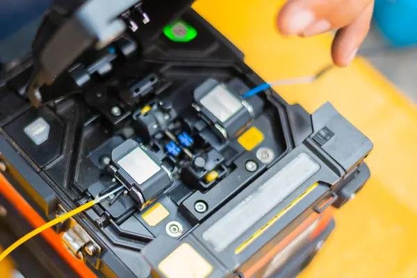
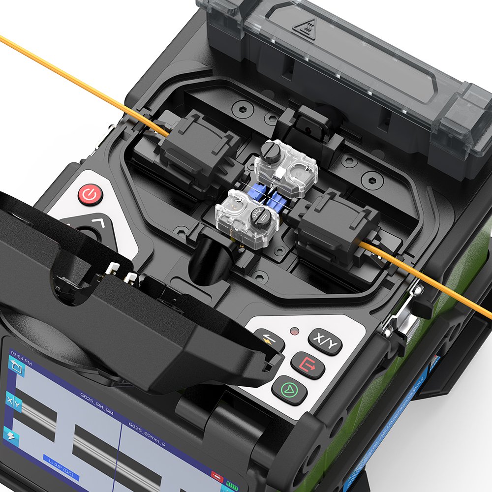
Role of Fiber Optic Splicer Machines
The fiber optic splicer machine is the cornerstone of modern splicing, automating alignment and bonding for precision and efficiency. Here’s a technical overview:
- Core Alignment Technology: Uses dual-camera systems (400x–600x zoom) to detect core offsets down to 0.1 μm, adjusting in real-time with piezoelectric motors.
- Arc Control: Microprocessor-controlled arcs (10–20 mA, 2–15 seconds) ensure uniform melting, with feedback loops correcting for humidity (e.g., 20–80% RH).
- Splice Loss Estimation: Built-in OTDR (Optical Time-Domain Reflectometer) predicts loss (0.01–0.1 dB accuracy), aiding quality control.
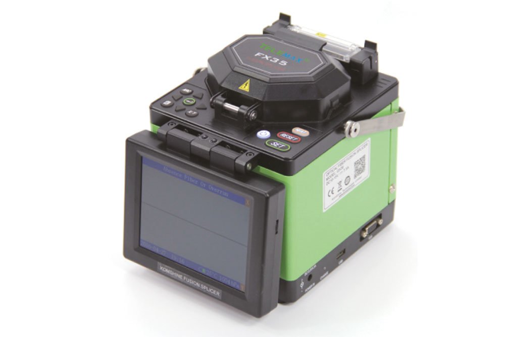
- Features: Touchscreens, battery operation (300–500 splices per charge), and data logging for 1000+ splices.
- Models: Examples include Fujikura 90S+ ($8000) and Sumitomo TYPE-71C+ ($6000), offering 6–9 seconds splice times.
- Applications: Mass deployment (e.g., 100 splices/day in rural broadband) and precision repairs.
Best Practices for Fiber Optic Splicing
To maximize splicing success, telecom professionals should follow these technical guidelines:
- Environmental Control
- Splice in clean, dry conditions (e.g., <50% RH, 10–30°C) to avoid condensation on fiber ends, which can increase loss by 0.2 dB.
- Use portable splice enclosures for outdoor splicing.
- Equipment Maintenance
- Calibrate fiber optic splicers weekly, checking electrode wear (replace after 4000 arcs). Dirty lenses can raise loss by 0.1 dB.
- Store machines at 0–40°C to preserve battery life.
- Quality Assurance
- Test each splice with an OTDR, targeting <0.1 dB loss and <-60 dB reflection.
- Visually inspect with 200x magnification for imperfections.
- Burial Considerations
- Splices should be housed in sealed enclosures (IP68-rated) and buried at 0.9–1.2 meters to protect against 50 kN/m² soil pressure.
- Use heat-shrink sleeves for fusion splices, adding 200 N tensile strength.
Image Placeholder 3: Splice Enclosure in Trench
Caption: A splice enclosure installed at 1.0-meter depth, showing sealed protection against moisture and soil pressure.
Challenges and Solutions in Fiber Optic Splicing
Splicing presents technical hurdles, but modern tools address them:
- Misalignment: Core offsets >0.5 μm cause 0.2 dB loss. Solution: Use fiber optic splicer machines with active alignment.
- Contamination: Dust particles (10 μm) scatter light. Solution: Clean with 99% isopropyl alcohol and lint-free wipes.
- Environmental Stress: Temperature cycles (e.g., -20°C to 60°C) weaken bonds. Solution: Use UV-cured resins or armored cables.
- Cost: High-end splicers ($5000+) limit small operators. Solution: Rent from vendors or use mechanical splices for low-traffic areas.
For cost-effective splicing solutions, contact CommMesh’s experienced engineers today.
Conclusion
The principle of fiber optic splicing—aligning and bonding fiber cores with minimal loss—underpins reliable telecom networks. Whether using fusion splicing with a fiber optic splicer machine for 0.01 dB precision or mechanical splicing for quick repairs, the process demands technical expertise and quality tools. For telecom companies and distributors, mastering splicing enhances network uptime and scalability. Discover advanced fiber optic splicers and support at CommMesh, where technology meets connectivity.
