In the intricate and rapidly evolving landscape of fiber optic infrastructure, two components frequently appear in network design discussions: the fiber patch panel and the ODF (Optical Distribution Frame). While both serve as termination, organization, and interconnection points for optical fibers, their scale, design philosophy, functionality, deployment environments, and use cases differ profoundly.
As of January 2026, with global fiber deployments exceeding 1.6 billion fiber-kilometers annually, FTTH connections surpassing 2.5 billion households, and data centers adopting 800G/1.6T interconnects requiring ultra-high-density management, understanding the precise differences between a fiber patch panel na ODF is essential for efficient architecture, cost optimization, scalability, and long-term reliability.
This extended definitive guide examines every facet of the Fiber Patch Panel vs ODF comparison. We define each component in depth, explore construction and design variations, compare technical specifications and performance metrics, analyze applications across industries with real-world examples, provide detailed installation methodologies and best practices, evaluate cost implications including total cost of ownership (TCO), present case studies from global deployments, debunk common myths and misconceptions, address compatibility, migration strategies, and hybrid scenarios, and forecast innovations shaping these products through 2030.
1. Defining the Two Components: Core Purposes, Functions, and Historical Context
1.1 What Is a Fiber Optic Patch Panel?
A fiber optic patch panel (also known as fiber distribution panel, fiber patch bay, optical patch panel, au fiber termination panel) is a modular, rack-mountable unit designed for high-density fiber termination, organization, and cross-connection in structured cabling environments.
Primary functions:
- Terminate incoming backbone, feeder, or horizontal cables.
- Provide modular adapter interfaces (SC, LC, MPO, etc.) for patching to equipment pigtails or jumpers.
- Enable flexible reconfiguration through patch cords without new splicing.
- Organize splices using internal trays and manage slack with routing rings.
- Serve as interconnection hubs in horizontal or backbone cabling hierarchies.
Typical locations:
- Data centers (main distribution area/MDA, intermediate distribution area/IDA, horizontal distribution area/HDA).
- Enterprise main distribution frames (MDF) and intermediate distribution frames (IDF).
- Telecom equipment rooms.
- Campus backbone distribution points.
- Broadcast and CATV facilities.
Patch panels act as the flexible “workhorse” for day-to-day fiber management, allowing technicians to perform moves, adds, and changes (MACs) quickly and efficiently.
Historical context: Patch panels evolved from copper telephone cross-connect blocks in the 1990s, adapting to fiber with the rise of structured cabling standards like TIA/EIA-568. The introduction of LC connectors in the early 2000s dramatically increased density, making patch panels essential for data center growth.
1.2 What Is an ODF (Optical Distribution Frame)?
An ODF (Optical Distribution Frame) is a large-scale, centralized fiber management system that integrates termination, splicing, patching, and distribution in a dedicated frame or cabinet.
Primary functions:
- High-capacity termination of incoming feeder cables from external plant.
- Mass splicing between feeder and internal distribution cables.
- Cross-connection between different network segments or customers.
- Integration of passive components like splitters for PON architectures.
- Comprehensive cable routing, slack management, and protection for thousands of fibers.
Typical locations:
- Telecom central offices and headends.
- National or regional backbone nodes.
- Large data center main distribution areas (MDA).
- Carrier-neutral facilities and colocation hubs.
ODFs serve as the “command center” for massive fiber counts, providing structured hierarchy and long-term organization.
Historical context: ODFs originated in the 1980s for telecom main distribution frames, evolving from copper MDFs. The 1990s–2000s saw ODFs become standard for FTTH feeder distribution, with modern ODFs incorporating modular trays and high-density adapters.
1.3 Fundamental Comparison Table
| Kipengele | Fiber Optic Patch Panel | Optical Distribution Frame (ODF) |
|---|---|---|
| Primary Role | Modular cross-connect and local distribution | Centralized high-capacity termination and routing |
| Scale | Small to medium (1U–6U, 24–576 ports) | Large (full rack/cabinet, 576–5000+ fibers) |
| Location | Rack in equipment room/data center | Dedicated ODF room or large telecom facility |
| Port Density | High per rack unit | High overall but lower per unit height |
| Reconfiguration Flexibility | High (easy front patching) | Structured (may require rear access) |
| Uwezo wa Kugawanyika | Limited (1–4 trays) | High (dozens of trays) |
| Cable Entry | Rear glands | Multiple large entry points |
| Typical Users | Enterprises, data centers, small telecom | Major operators, national backbones |
| Future Scalability | High (modular stacking) | Very high (designed for expansion) |
2. Detailed Construction and Design Differences
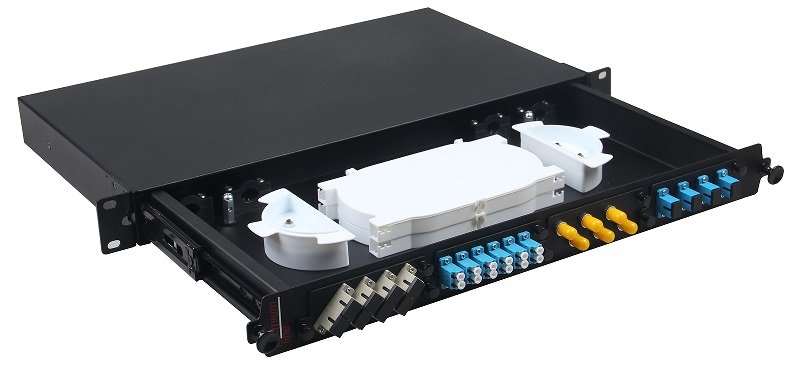
2.1 Fiber Optic Patch Panel Construction
Patch panels are built for modularity and rack integration.
- Chassis Material: Cold-rolled steel or aluminum with powder coating for durability and EMI shielding.
- Front Panel: Modular adapter plates supporting SC, LC, MPO, ST, E2000, etc., with color-coded dust shutters and clear labeling strips.
- Rear Access: Multiple cable entry points with rubber glands, strain relief boots, grounding bars, and cable tie points.
- Internal Features: Sliding or fixed splice trays (24–48 splices per tray), cable routing rings, slack storage spools, vertical/horizontal cable managers.
- Variants:
- Loaded (pre-installed adapters/pigtails)
- Unloaded (empty for custom configuration)
- High-density sliding drawer for rear access
- Angled panels for improved cable routing
- Pre-terminated with MPO trunks for data center
Modern 2026 panels include tool-less adapter plate installation, integrated cable management arms, and optional smart monitoring ports.
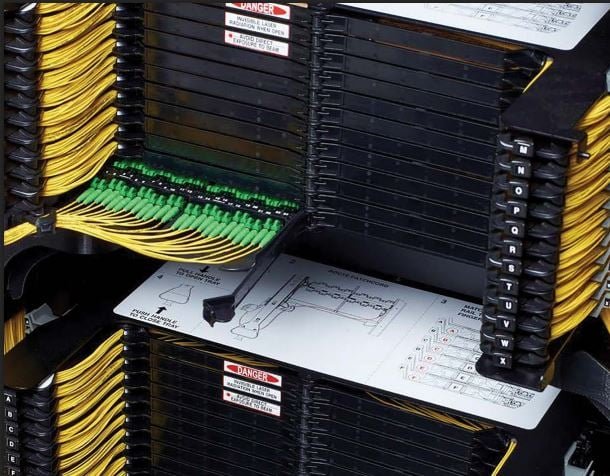
2.2 ODF Construction
ODFs are large-scale systems for centralized management.
- Frame Structure: Full-height 19-inch or 21-inch rack or dedicated cabinet with reinforced base for stability.
- Modules: Swing-out or sliding frames containing splice trays, splitter holders, and adapter panels.
- Uelekezaji wa Cable: Extensive vertical and horizontal cable managers, overhead troughs, and under-floor routing options.
- Doors and Security: Lockable front/rear doors with ventilation and cable access grommets.
- Integration Features: Built-in splitter modules, monitoring ports, grounding busbars, and labeling systems.
ODFs often include seismic bracing for earthquake-prone regions.
2.3 Size, Form Factor, and Capacity Comparison
Patch panels: Standardized 19-inch width, 1U (44 mm) to 6U height, supporting 96–576 ports.
ODFs: Full cabinets (42U–48U height), accommodating 1000–5000+ fibers with multiple modules.
Patch panels excel in density per rack unit; ODFs in overall capacity and structured organization.
3. Functionality and Technical Specifications
3.1 Capacity and Scalability
Patch panels scale by stacking multiple units in racks.
ODFs provide integrated scalability within a single frame.
3.2 Optical Performance
Both support premium adapters with ≤0.15 dB insertion loss and ≥65 dB return loss (APC).
3.3 Environmental Protection
Patch panels: Indoor IP20/IP40.
ODFs: Indoor with optional seismic and fire ratings.
3.4 Cable Management and Re-entry
Patch panels: Front-focused for quick patching.
ODFs: Rear/front access with swing-out modules for large-scale re-entry.
3.5 Splicing and Termination Options
Patch panels: Limited trays for local splicing.
ODFs: High-capacity trays for feeder splicing.
4. Applications and Use Cases Across Industries
4.1 Fiber Optic Patch Panel Applications
- Vituo vya Data: High-density cross-connect between core switches, servers, and storage.
- Mitandao ya Biashara: MDF/IDF for structured cabling to work areas.
- Small Telecom Nodes: Local distribution in regional offices.
- Broadcast Facilities: Video headend patching.
- Campus Networks: Building-to-building links.
4.2 ODF Applications
- Telecom Central Offices: Feeder cable termination and PON OLT distribution.
- National Backbone Nodes: High-count splicing for long-haul.
- Large Data Center MDA: Main distribution for thousands of fibers.
- Carrier Hotels: Interconnection between operators.
4.3 Hybrid and Overlapping Scenarios
Many facilities use ODF for feeder termination and patch panels for distribution.
5. Installation and Deployment Methodologies
5.1 Installing a Fiber Optic Patch Panel
- Rack mounting with proper alignment.
- Rear cable entry and strain relief.
- Adapter plate installation.
- Pigtail splicing or pre-terminated loading.
- Front labeling and testing.
5.2 Installing an ODF
- Frame assembly and anchoring.
- Feeder cable routing through entry points.
- Mass splicing in trays.
- Cross-connect patching.
- Documentation and testing.
6. Cost Analysis and Total Cost of Ownership 2026
6.1 Upfront Pricing
| Item | Patch Panel Price | ODF Price |
|---|---|---|
| 96-port high-density | $300–$600 | N/A |
| Full ODF (2000 fibers) | N/A | $5,000–$12,000 |
6.2 Total Cost of Ownership
Patch panels lower per-port cost at scale.
ODFs higher initial but structured for long-term.
7. Advantages and Limitations
7.1 Patch Panel
Advantages: Flexible, modular, easy MACs. Limitations: Limited capacity per unit.
7.2 ODF
Advantages: High capacity, structured organization. Limitations: Higher cost, space requirements.
8. Innovations and Trends 2026–2030
- Modular ODF with hot-swappable trays
- High-density patch panels with AI routing
- Smart monitoring integration
CommMesh leads with hybrid solutions.
Conclusion: Choosing the Right Solution
Fiber optic patch panels for modular distribution; ODF for large-scale centralized management.
CommMesh offers both — contact us for your needs.
