The global fiber optic network, exceeding 1.8 million km as of 2025, relies on innovative technologies to meet escalating bandwidth demands from 5G, cloud computing, and IoT. Wavelength Division Multiplexing (WDM) stands out as a cornerstone, enabling multiple data streams to travel simultaneously over a single fiber. This guide delves into the principles, types, applications, and future trends of WDM. Tailored for professionals sourcing solutions from CommMesh, it provides a comprehensive understanding to optimize high-capacity networks.
Introduction to Wavelength Division Multiplexing (WDM)
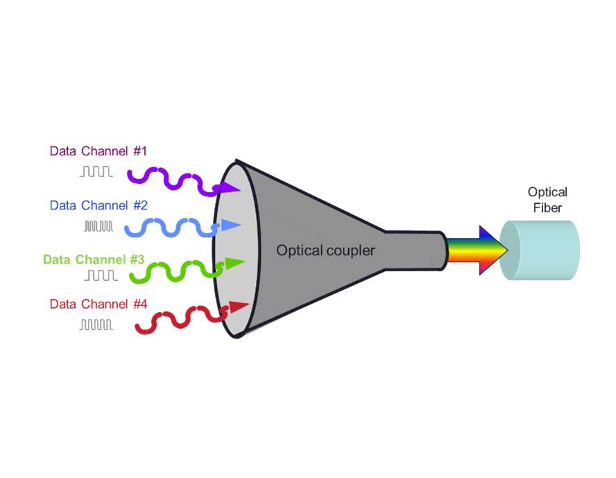
Wavelength Division Multiplexing (WDM) is a fiber optic transmission technique that combines multiple optical signals at different wavelengths into a single fiber, significantly increasing its capacity. Each wavelength, or “channel,” carries an independent data stream, allowing bandwidths up to 400 Gbps per channel, with aggregate capacities reaching terabits per second (Tbps) when using multiple channels. Introduced in the 1980s, WDM has evolved from basic systems to sophisticated implementations supporting modern telecommunications. As of 2025, with data traffic doubling every 18–24 months (per Cisco), WDM is indispensable for long-haul, metro, and access networks.
Principles of Wavelength Division Multiplexing
WDM operates by exploiting the vast bandwidth of optical fibers, which can support thousands of wavelengths within the 1260–1675 nm range, limited by fiber attenuation (e.g., 0.2 dB/km at 1550 nm). The core principles include:
- Wavelength Allocation
- Each channel uses a distinct wavelength, spaced 0.8 nm (100 GHz) or 0.4 nm (50 GHz) apart in the C-band (1530–1565 nm) or L-band (1565–1625 nm), per the ITU-T G.694.1 grid.
- Example: 40 channels at 100 GHz spacing yield 16 Tbps with 400 Gbps per channel.
- Multiplexing and Demultiplexing
- Multiplexing: A multiplexer (MUX) combines wavelengths using thin-film filters or arrayed waveguide gratings (AWGs), ensuring <0.5 dB insertion loss.
- Demultiplexing: A demultiplexer (DEMUX) separates wavelengths at the receiver, with crosstalk below -30 dB.
- Technical Note: Optical amplifiers (e.g., EDFAs) boost signals every 80–100 km, compensating for 20–25 dB loss.
- Light Propagation
- Signals travel via total internal reflection in the fiber core (refractive index ~1.46), with dispersion (e.g., 17 ps/nm/km) managed by dispersion-compensating fiber (DCF).
- Nonlinear effects like four-wave mixing are minimized with precise wavelength spacing.
Types of Wavelength Division Multiplexing
WDM variants cater to different capacity and cost needs:
- Coarse Wavelength Division Multiplexing (CWDM)
- Principle: Uses wider wavelength spacing (20 nm, e.g., 1470–1610 nm), supporting 18 channels with 2.5–10 Gbps each.
- Advantages: Lower cost ($500–$2000 per MUX) and simpler optics, with <3 dB loss.
- Applications: Short-haul (50–80 km) metro networks and campus links.
- Limitations: Limited to 8–18 channels due to broader spacing, per ITU-T G.694.2.
- Dense Wavelength Division Multiplexing (DWDM)
- Principle: Employs narrow spacing (0.8 nm or 100 GHz, e.g., 1530–1565 nm), supporting 40–96 channels with 10–400 Gbps each.
- Advantages: High capacity (up to 96 Tbps), with <0.5 dB loss per channel, amplified by EDFAs every 80 km.
- Applications: Long-haul (100–3000 km) and backbone networks.
- Limitations: Higher cost ($5000–$10,000 per system) and complex temperature control (±0.1°C).
- Bidirectional WDM (BWDM)
- Principle: Uses the same fiber for upstream and downstream traffic on different wavelengths (e.g., 1310 nm and 1550 nm).
- Advantages: Doubles capacity on existing fibers, with <1 dB loss.
- Applications: FTTH (Fiber to the Home) and small-scale networks.
- Limitations: Susceptible to 0.2 dB crosstalk, requiring precise filters.
Technical Components of WDM Systems
WDM relies on specialized hardware:
- Transmitters and Receivers
- Lasers emit specific wavelengths (e.g., 1550.12 nm) with ±0.1 nm stability, modulated at 10–400 Gbps using NRZ or QAM.
- Receivers use photodiodes to detect signals, with sensitivity of -28 dBm.
- Optical Add-Drop Multiplexers (OADMs)
- OADMs add or drop individual wavelengths (e.g., 1550.92 nm) with <0.3 dB loss, enabling network flexibility.
- Used in ring topologies for 99.9% uptime.
- Amplifiers
- Erbium-Doped Fiber Amplifiers (EDFAs) boost 20–30 dB every 80–100 km, operating in the C-band with 5–7 dB noise figure.
- Raman amplifiers extend reach to 150 km with 15–20 dB gain.
- Dispersion Compensation
- DCF modules correct 17 ps/nm/km dispersion, ensuring signal integrity over 1000 km.
- Technical Note: Adds 0.5–1 dB loss but prevents 10% signal distortion.
Applications of Wavelength Division Multiplexing
WDM’s versatility makes it integral to various network architectures as of 2025:
- Long-Haul and Backbone Networks
- DWDM systems support transoceanic cables, with 96 channels delivering 38.4 Tbps over 10,000 km, amplified every 80 km. Example: The 2025 Asia-Pacific Cable Network (APCN-3) uses DWDM to handle 50 Tbps, per TeleGeography.
- Technical Note: EDFAs maintain signal-to-noise ratios (SNR) above 20 dB, ensuring error rates below 10^-12.
- Metro and Access Networks
- CWDM is ideal for 50–80 km urban rings, with 8–18 channels at 10 Gbps each, reducing costs by 40% compared to DWDM. Example: Verizon’s metro deployments in U.S. cities use CWDM for 5G fronthaul, supporting 100 Gbps links.
- BWDM enables FTTH, with bidirectional 1310/1550 nm wavelengths delivering 1 Gbps per home.
- Data Centers
- DWDM interconnects racks over 100 meters, with 40 channels at 400 Gbps totaling 16 Tbps. Hyperscale facilities like those from Amazon Web Services (AWS) rely on DWDM for cloud traffic, handling petabytes daily.
- Technical Note: OADMs allow dynamic channel dropping, with reconfiguration times under 50 ms.
- Enterprise and Campus Networks
- CWDM connects buildings at 10 Gbps per channel, with low-cost MUX/DEMUX units. Example: Universities in Europe use CWDM for campus-wide networks, per ETSI reports.
Performance Metrics of WDM Systems
WDM performance is evaluated through key parameters:
- Channel Capacity and Bandwidth
- DWDM offers 40–96 channels (up to 96 Tbps aggregate), with per-channel rates of 10–400 Gbps using coherent modulation (e.g., QPSK or 16-QAM).
- CWDM limits to 18 channels (up to 180 Gbps), suitable for cost-sensitive setups.
- Technical Note: Spectral efficiency reaches 4–8 bits/s/Hz in DWDM, per ITU-T G.694.1.
- Attenuation and Reach
- Fiber loss (0.2 dB/km at 1550 nm) is compensated by EDFAs (20–30 dB gain), extending reach to 1000 km without regeneration.
- Dispersion (17 ps/nm/km) is mitigated by DCF, keeping bit error rates (BER) below 10^-9.
- Difference: CWDM reach is 80 km without amplification, vs. DWDM’s 3000 km with Raman amps.
- Crosstalk and Noise
- Channel crosstalk is kept below -30 dB with AWG filters, while EDFA noise figures (4–6 dB) limit SNR to 20–25 dB.
- Nonlinear effects like self-phase modulation (SPM) are managed with power levels <5 dBm per channel.
- Reliability and Latency
- WDM systems achieve 99.999% uptime with redundant amplifiers, adding <0.1 ms latency per MUX/DEMUX.
- Technical Note: OSNR (optical signal-to-noise ratio) must exceed 20 dB for 400 Gbps transmission.
| Metric | CWDM | DWDM | BWDM |
|---|---|---|---|
| Channels | 8–18 | 40–96 | 2–4 |
| Bandwidth (Gbps/channel) | 2.5–10 | 10–400 | 1–10 |
| Reach (km) | 50–80 | 100–3000 | 20–50 |
| Insertion Loss (dB) | <3 | <0.5 | <1 |
| Cost ($ per MUX) | 500–2000 | 5000–10000 | 100–500 |
Challenges in Implementing WDM
WDM deployment faces several technical obstacles:
- Cost and Complexity
- DWDM systems cost $50,000–$100,000 per node due to precise lasers and amplifiers. Solution: CWDM for budget-conscious networks, reducing costs by 50%.
- Complexity in temperature control (±0.1°C) for wavelength stability adds operational overhead.
- Dispersion and Nonlinear Effects
- Chromatic dispersion (17 ps/nm/km) degrades signals over 100 km, causing 10% BER increase. Solution: DCF or digital signal processing (DSP) chips correct 90% of effects.
- Four-wave mixing (FWM) at high powers (>5 dBm) generates crosstalk. Solution: Uneven channel spacing or polarization multiplexing.
- Amplification Limitations
- EDFAs amplify only C-band (1530–1565 nm), limiting channels. Solution: Raman amplifiers extend to L-band (1565–1625 nm), adding 40 channels.
- Noise accumulation reduces OSNR by 5 dB per amplifier stage. Solution: Forward error correction (FEC) improves BER by 10^-6.
- Scalability Issues
- Adding channels mid-network requires OADMs, with 0.3 dB loss each. Solution: Reconfigurable OADMs (ROADMs) enable dynamic addition in <1 minute.
- Spectrum exhaustion in dense urban fibers. Solution: Flexible grid WDM (flexi-WDM) with 12.5 GHz spacing doubles capacity.
Future Trends in Wavelength Division Multiplexing
WDM is evolving to meet 2025’s data explosion:
- Super-Dense WDM (SD-WDM)
- Supports 200+ channels with 25 GHz spacing, achieving 80 Tbps per fiber. Prototypes from Huawei target 2026 deployment.
- Technical Note: Uses advanced DSP for 8 bits/s/Hz efficiency.
- Coherent WDM
- Employs phase modulation (e.g., DP-QPSK) for 800 Gbps per channel over 1000 km, with OSNR >25 dB. Adopted in 40% of new long-haul links (per TeleGeography).
- Solution for nonlinear effects: Adaptive equalization reduces distortion by 20%.
- Integrated Photonics
- Silicon photonics MUX/DEMUX chips reduce size by 50% and cost by 30%, enabling compact systems for data centers.
- Example: Intel’s 2025 chips support 100 channels with 0.2 dB loss.
- AI-Optimized WDM
- AI algorithms predict channel allocation, improving spectrum utilization by 25% and reducing power consumption by 15%. Trials by Nokia show 99.99% uptime.
- Technical Note: Machine learning models analyze OSNR in real-time for dynamic reconfiguration.
Conclusion
Wavelength Division Multiplexing (WDM) revolutionizes fiber optics by multiplexing multiple wavelengths (e.g., 1310–1550 nm) over a single fiber, achieving Tbps capacities with low loss (0.2 dB/km). From CWDM for cost-effective metro networks to DWDM for high-density backbones, WDM’s principles of multiplexing, amplification, and dispersion compensation drive modern telecommunications. Despite challenges like cost and nonlinear effects, solutions like ROADMs and DSP ensure scalability. Future trends, including SD-WDM and AI integration, promise even greater efficiency. For WDM solutions, explore CommMesh.
